Nissan Titan A60. Manual - part 586


  Index      Nissan     Nissan Titan A60 (2011 year) - Service and Repair Manual


Search            


Content   ..  584  585  586  587   ..


Nissan Titan A60. Manual - part 586


AIR MIX DOOR MOTOR

HAC-27

< DTC/CIRCUIT DIAGNOSIS >

[AUTOMATIC AIR CONDITIONER]

C

D

E

F

G

H

J

K

L

M

A

B

HAC

N

O

P

AIR MIX DOOR MOTOR

System Description

INFOID:0000000006164688

SYSTEM DESCRIPTION

SYMPTOM:

• Discharge air temperature does not change.

• Air mix door motor does not operate.

SYSTEM DESCRIPTION

Component Parts

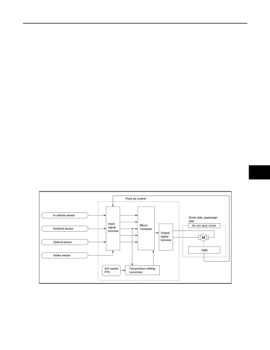
Air mix door control system components are:

• Front air control

• Air mix door motors (driver, passenger)

• PBR (built-into air mix door motors)

• In-vehicle sensor

• Ambient sensor

• Optical sensor

• Intake sensor

System Operation

The front air control receives data from the temperature selected by the driver side, passenger side, and rear.

The front air control then applies a voltage to one circuit of the appropriate air mix door motor, while ground is

applied to the other circuit, causing the appropriate air mix door motor to rotate. The direction of rotation is

determined by which circuit has voltage applied to it, and which one has ground applied to it. The front air con-

trol monitors the air mix door positions by measuring the voltage signal on the PBR circuits of each door.

In AUTO mode the air mix, intake, mode door, and defrost door positions are set by the front air control which

determines the proper position based on inputs from the in-vehicle sensor, ambient sensor, optical sensor,

intake sensor, and the temperature selected by the driver and front and rear passengers.

Subsequently, HOT/COLD or DEFROST/VENT or FRESH/RECIRCULATION operation is selected. The new

door position data is returned to the front air control

AWIIA0372GB

HAC-28

< DTC/CIRCUIT DIAGNOSIS >

[AUTOMATIC AIR CONDITIONER]

AIR MIX DOOR MOTOR

Air Mix Door Control Specification

COMPONENT DESCRIPTION

Air Mix Door Motors

The driver (1) and passenger (2) air mix door motors are attached to

the front heater & cooling unit assembly. These motors rotate so that

the air mix door is opened or closed to a position set by the front air

control. Motor rotation is then conveyed through a shaft and the air

mix door position is then fed back to the front air control by the PBR

built into the air mix door motors.

Air Mix Door Motor (Driver) Component Function Check

INFOID:0000000006164689

INSPECTION FLOW

1.

CONFIRM SYMPTOM BY PERFORMING OPERATIONAL CHECK - TEMPERATURE INCREASE

1. Turn the temperature control dial (driver) clockwise until 32

°C (90°F) is displayed.

2. Check for hot air at discharge air outlets.

>> GO TO 2.

2.

CONFIRM SYMPTOM BY PERFORMING OPERATIONAL CHECK - TEMPERATURE DECREASE

1. Turn the temperature control dial (driver) counterclockwise until 18

°C (60°F) is displayed.

2. Check for cold air at discharge air outlets.
Can a symptom be duplicated?

YES

>> Inspection End.

NO

>> Go to diagnosis procedure. Refer to 

HAC-28, "Air Mix Door Motor (Driver) Diagnosis Procedure"

.

Air Mix Door Motor (Driver) Diagnosis Procedure

INFOID:0000000006708575

Regarding Wiring Diagram information, refer to 

HAC-71, "Wiring Diagram - Automatic Air Conditioner"

.

SYMPTOM:

• Discharge air temperature does not change.

• Air mix door motor does not operate.

1.

CHECK AIR MIX DOOR MOTOR (DRIVER) POSITION BALANCED RESISTOR (PBR) FEEDBACK VOLT-

AGE
1. Turn ignition switch ON.

WJIA0435E

AWIIA0109ZZ

AIR MIX DOOR MOTOR

HAC-29

< DTC/CIRCUIT DIAGNOSIS >

[AUTOMATIC AIR CONDITIONER]

C

D

E

F

G

H

J

K

L

M

A

B

HAC

N

O

P

2. Using CONSULT-III, check "DVR MIX FDBCK" in "DATA MONITOR" mode in "HVAC". Refer to 

HAC-17,

"CONSULT-III Function (HVAC)"

.

3. Observe "DVR MIX FDBACK" voltage while rotating temperature control dial (driver) between 32

°C (90°F)

and 18

°C (60°F).

Is the inspection result normal?

YES

>> • Air mix door motor (driver) is OK.

• Inspect air mix door (driver) for mechanical failure and repair if necessary. If air mix door (driver)

is OK, refer to 

HAC-83, "Component Function Check"

 for insufficient cooling or 

HAC-91, "Com-

ponent Function Check"

 for insufficient heating.

NO

>> GO TO 2.

2.

CHECK AIR MIX DOOR MOTOR (DRIVER) CIRCUITS FOR OPEN AND SHORT TO GROUND 

1. Turn ignition switch OFF.

2. Disconnect the front air control harness connector M49 (A) and

the air mix door motor (driver) harness connector M147 (B).

3. Check continuity between front air control harness connector

M49 (A) terminals 17, 18 and the air mix door motor (driver) har-

ness connector M147 (B) terminals 1, 6.

4. Check continuity between front air control harness connector

M49 terminals 17, 18 and ground.

Is the inspection result normal?

YES

>> GO TO 3.

NO

>> Repair or replace harness as necessary.

3.

CHECK FRONT AIR CONTROL FOR AIR MIX DOOR MOTOR (DRIVER) POWER AND GROUND 

1. Reconnect front air control harness connector.

2. Turn ignition switch ON.

3. Rotate temperature control dial (driver) to 32

°C (90°F).

4. Check voltage between front air control harness connector M49

terminal 17 and terminal 18 while rotating temperature control

dial (driver) to 18

°C (60°F) and back to 32°C (90°F).

Is the inspection result normal?

Monitor Item

Condition

Results

DVR MIX FDBCK

Rotate temperature control dial (driver) be-

tween 32

°C (90°F) and 18°C (60°F)

Voltage varies with dial rotation between 0.2 and 4.8 

volts.

A

B

Continuity

Connector

Terminal

Connector

Terminal

M49

17

M147

1

Yes

18

6

Connector

Terminal

Continuity

M49

17

Ground

No

18

AWIIA0377ZZ

AWIIA0374ZZ

Connector

Terminals

Condition Voltage 

(Approx.)

(+) (-)

M49

17

18

While rotating temperature control 

dial (driver) from 32

°C (90°F) to 18°C 

(60

°F)

Battery voltage

18

17

While rotating temperature control 

dial (driver) from 18

°C (60°F) to 32°C 

(90

°F)

Battery voltage

AWIIA0373ZZ

HAC-30

< DTC/CIRCUIT DIAGNOSIS >

[AUTOMATIC AIR CONDITIONER]

AIR MIX DOOR MOTOR

YES

>> GO TO 4.

NO

>> Replace front air control. Refer to 

VTL-8, "Removal and Installation"

.

4.

CHECK AIR MIX DOOR MOTOR (DRIVER) PBR CIRCUITS FOR OPEN AND SHORT TO GROUND 

1. Turn ignition switch OFF.

2. Disconnect the front air control harness connectors.

3. Check continuity between front air control harness connector

M49 (C) terminal 3, connector M50 (A) terminal 28 and air mix

door motor (driver) harness connector M147 (B) terminals 3, 2.

4. Check continuity between front air control harness connector

M49 (C) terminal 3, M50 (A) terminal 28 and ground.

Is the inspection result normal?

YES

>> GO TO 5.

NO

>> Repair or replace harness as necessary.

5.

CHECK PBR FEEDBACK SIGNAL CIRCUIT FOR OPEN AND SHORT TO GROUND 

1. Check continuity between front air control harness connector

M49 (A) terminal 6 and air mix door motor (driver) harness con-

nector M147 (B) terminal 4.

2. Check continuity between front air control harness connector

M49 terminal 6 and ground.

Is the inspection result normal?

YES

>> GO TO 6.

NO

>> Repair or replace harness as necessary.

6.

CHECK FRONT AIR CONTROL FOR 5 VOLT REFERENCE (VREF), VREF RETURN, AND FEEDBACK

SIGNAL 

A and C

B

Continuity

Connector

Terminal

Connector

Terminal

M49 (C)

3

M147

2

Yes

M50 (A)

28

3

Connector

Terminal

Continuity

M49 (C)

3

Ground

No

M50 (A)

28

AWIIA0393ZZ

A

B

Continuity

Connector

Terminal

Connector

Terminal

M49

6

M147

4

Yes

AWIIA0384ZZ

Connector

Terminal

Continuity

M49

6

Ground

No

AWIIA0383ZZ


Content   ..  584  585  586  587   ..