Nissan Titan A60. Manual - part 585
MODE DOOR MOTOR
HAC-23
< DTC/CIRCUIT DIAGNOSIS >
[AUTOMATIC AIR CONDITIONER]
C
D
E
F
G
H
J
K
L
M
A
B
HAC
N
O
P
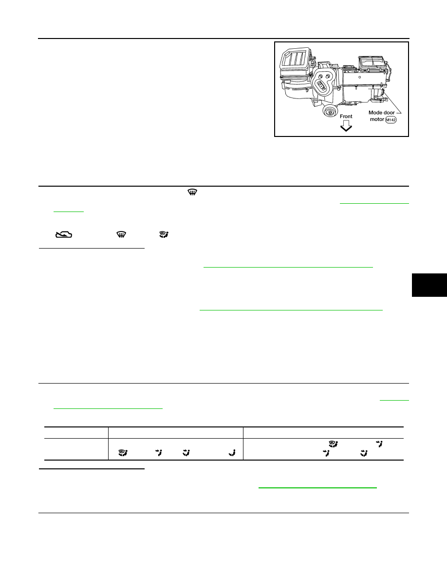
The mode door motor is attached to the heater & cooling unit assem-
bly. It rotates so that air is discharged from the outlet as indicated by
the front air control. Motor rotation is conveyed to a link which acti-
vates the mode door.
Mode Door Motor Component Function Check
INFOID:0000000006164686
INSPECTION FLOW
1.
CONFIRM SYMPTOM BY PERFORMING OPERATIONAL CHECK - DISCHARGE AIR
1. Press each mode switch and press the
(DEF) switch. Each position indicator should illuminate.
2. Confirm that discharge air comes out according to the air distribution table. Refer to
.
NOTE:
Confirm that the compressor clutch is engaged (visual inspection) and intake door position is at FRESH
when DEF (
) or D/F (
) is selected.
Is the inspection result normal?
YES
>> Inspection End.
NO
>> Go to diagnosis procedure. Refer to
HAC-23, "Mode Door Motor Diagnosis Procedure"
.
Mode Door Motor Diagnosis Procedure
INFOID:0000000006708574
Regarding Wiring Diagram information, refer to
HAC-71, "Wiring Diagram - Automatic Air Conditioner"
SYMPTOM:
• Air outlet does not change.
• Mode door motor does not operate normally.
1.
CHECK MODE DOOR MOTOR POSITION BALANCED RESISTOR (PBR) FEEDBACK VOLTAGE
1. Turn ignition switch ON.
2. Using CONSULT-III, check "MODE FDBCK" in "DATA MONITOR" mode in "HVAC". Refer to
.
3. Observe "MODE FDBCK" voltage while cycling front air control mode switch through all modes.
Is the inspection result normal?
YES
>> • Mode door motor is OK.
• Inspect mode door for mechanical failure. Refer to
VTL-19, "Removal and Installation"
NO
>> GO TO 2.
2.
CHECK MODE DOOR MOTOR CIRCUITS FOR OPEN AND SHORT TO GROUND
WJIA0587E
Monitor Item
Condition
Results
MODE FDBCK
Cycle mode switch through all modes, D/F
(
), VENT (
), B/L (
), and FOOT(
)
Voltage varies between D/F (
) and VENT (
), and
between VENT (
) and B/L (
).