Nissan Titan A60. Manual - part 533


  Index      Nissan     Nissan Titan A60 (2011 year) - Service and Repair Manual


Search            


Content   ..  531  532  533  534   ..


Nissan Titan A60. Manual - part 533


PREPARATION

FAX-3

< PREPARATION >

C

E

F

G

H

I

J

K

L

M

A

B

FAX

N

O

P

PREPARATION

PREPARATION

Special Service Tool

INFOID:0000000006161620

The actual shapes of Kent-Moore tools may differ from those of special service tools illustrated here.

Commercial Service Tool

INFOID:0000000006161621
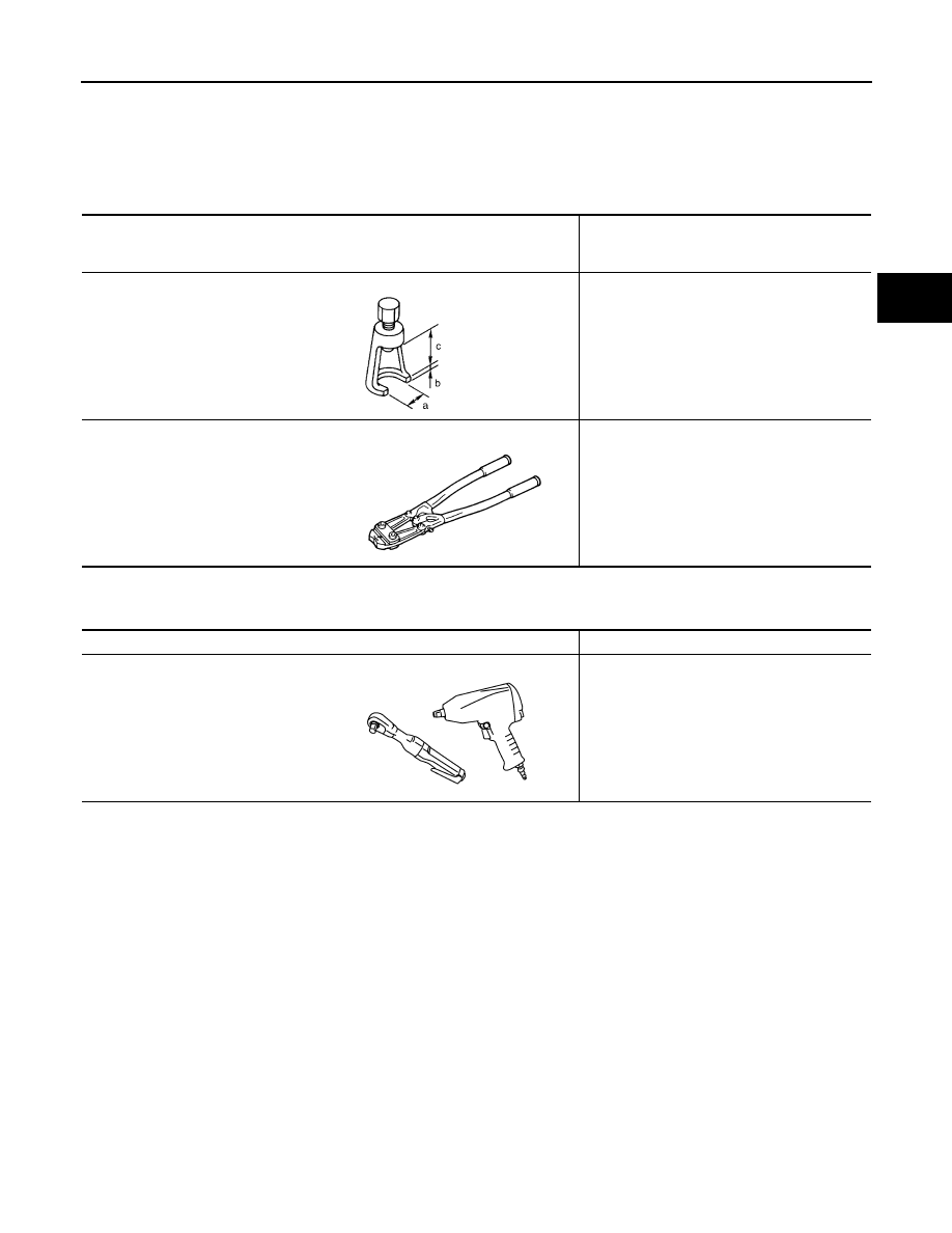
Tool number
(Kent-Moore No.)
Tool name

Description

ST29020001
(J-24319-01)
Gear arm puller

Removing ball joint for steering knuckle
a: 34 mm (1.34 in)
b: 6.5 mm (0.256 in)
c: 61.5 mm (2.421 in)

KV40107300
(

)

Boot band crimping tool

Installing boot bands

NT694

ZZA1229D

Tool name

Description

Power tools

Removing bolts and nuts

PBIC0190E

FAX-4

< SYMPTOM DIAGNOSIS >

NOISE, VIBRATION, AND HARSHNESS (NVH) TROUBLESHOOTING

SYMPTOM DIAGNOSIS

NOISE, VIBRATION, AND HARSHNESS (NVH) TROUBLESHOOTING

NVH Troubleshooting Chart

INFOID:0000000006161622

Use the chart below to help you find the cause of the symptom. If necessary, repair or replace these parts.

×: Applicable

Reference page

FAX-8

F

AX-10

F

AX-10

FAX-8

FAX-5

DLN-130, "

NVH T

rou

bl

es

ho

ot

in

g Cha

rt

"

 (2

F1

31

0)

DLN-163, "

NVH T

rou

bl

es

ho

ot

in

g Cha

rt

"

Re

fer 

to 

DRI

VE SHAF

T in

 th

is cha

rt.

Re

fer 

to 

WHEEL

 HUB in

 th

is cha

rt.

RSU-4, "

NV

H T

rou

ble

shoo

ting Cha

rt

"

WT

-4

2,

 "

NV

H T

rou

bl

es

ho

oti

ng

 Cha

rt

"

WT

-4

2,

 "

NV

H T

rou

bl

es

ho

oti

ng

 Cha

rt

"

BR

-5

, "

NV

H T

rou

bl

es

ho

oti

ng

 Cha

rt

"

ST

-5, "

NVH T

rou

bl

es

ho

ot

ing

 Cha

rt

"

Possible cause and SUSPECTED PARTS

Ex

ce

ss

iv

e j

oi

nt an

gl

e

Jo

in

t s

lid

in

g re

si

st

an

ce

Imb

al

anc

e

Im

pro

pe

r in

st

al

lat

ion

lo

ose

ness

P

art

s interference

W

he

el be

arin

g da

ma

ge

PR

OP

EL

LE

R

 S

H

A

F

T

FRO

N

T FINAL DRIVE

DRIV

E SHAFT

W

H

EEL H

U

B

S

U

S

PENSION

TI

RE

S

ROAD W

H

EEL

BR

AK

E

S

S

T

EERING

Symptom

DRIVE SHAFT

Noise, Vibration

×

×

×

×

×

×

×

×

×

×

Shake

×

×

×

×

×

×

×

×

×

WHEEL HUB

Noise

×

×

×

×

×

×

×

×

×

×

Shake

×

×

×

×

×

×

×

×

×

Vibration

×

×

×

×

×

×

×

Shimmy

×

×

×

×

×

×

×

Shudder

×

×

×

×

×

×

Poor quality ride or 
handling

×

×

×

×

×

×

WHEEL HUB

FAX-5

< PERIODIC MAINTENANCE >

C

E

F

G

H

I

J

K

L

M

A

B

FAX

N

O

P

PERIODIC MAINTENANCE

WHEEL HUB

On-Vehicle Inspection and Service

INFOID:0000000006161623

Make sure the mounting conditions (looseness, backlash) of each component and component status (wear,

damage) are normal.

WHEEL BEARING INSPECTION

• Move wheel hub in the axial direction by hand. Make sure there is

no looseness of wheel bearing.

• Rotate wheel hub and make sure there is no unusual noise or

other irregular conditions. If there are any irregular conditions,

replace wheel hub and bearing assembly.

Axial end 
play limit 

: Refer to 

FAX-15, "Wheel Bear-

ing"

.

SMA571A

FAX-6

< UNIT REMOVAL AND INSTALLATION >

WHEEL HUB

UNIT REMOVAL AND INSTALLATION

WHEEL HUB

Removal and Installation

INFOID:0000000006161624

REMOVAL

1. Remove wheel and tire using power tool.
2. Remove engine undercover if equipped, using power tool.
3. Without disassembling the hydraulic lines, remove the torque member bolts using power tool. Then repo-

sition brake caliper aside with wire. Refer to 

BR-32, "Removal and Installation of Brake Caliper and

Rotor"

.

NOTE:

Do not press brake pedal while brake caliper is removed.

4. Put alignment mark on disc rotor and wheel hub and bearing

assembly, then remove disc rotor.

5. Remove wheel sensor. Refer to 

BRC-113, "Removal and Installation"

.

• Inspect the wheel sensor O-ring, replace the wheel sensor assembly if damaged.

• Clean the wheel sensor hole and mounting surface with a suitable brake cleaner and clean lint-free

shop rag. Be careful that dirt and debris do not enter the axle bearing area.

• Apply a coat of suitable grease to the wheel sensor O-ring and mounting hole.

CAUTION:

Do not pull on the wheel sensor harness.

6. On 4WD models, remove drive shaft from steering knuckle. Refer to 

FAX-8, "Removal and Installation"

.

7. Remove wheel hub and bearing assembly bolts using power tool.

1.

Disc rotor

2.

Wheel hub and bearing assembly

3.

Wheel stud

4.

Splash guard

5.

Steering knuckle

Front

AWDIA0423GB

WDIA0044E


Content   ..  531  532  533  534   ..