Nissan Titan A60. Manual - part 477


  Index      Nissan     Nissan Titan A60 (2011 year) - Service and Repair Manual


Search            


Content   ..  475  476  477  478   ..


Nissan Titan A60. Manual - part 477


ENGINE UNIT

EM-93

< UNIT DISASSEMBLY AND ASSEMBLY >

C

D

E

F

G

H

I

J

K

L

M

A

EM

N

P

O

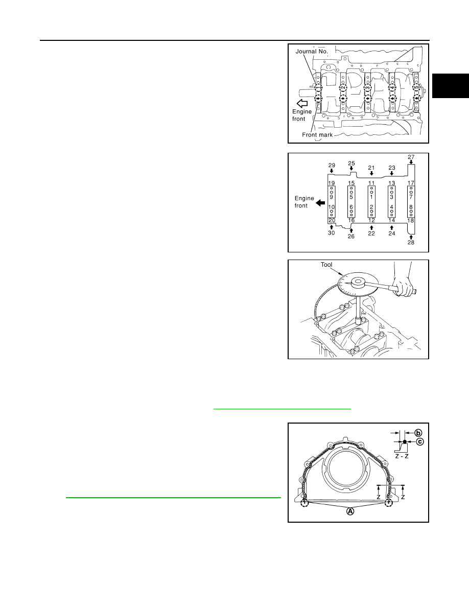
6. Install main bearing caps.

• Align the identification number to the journal position to install. 

• Install it with the front mark (indicated by the arrow) facing the

front of engine. 

• Tap caps lightly to seat them in the installation position.

7. Follow the steps below to tighten each main bearing cap bolt.
a. Apply engine oil to threads and seating surfaces of bolts, and

tighten all bolts temporarily.

b. Measure tightening angle using Tool.

CAUTION:

Measure tightening angle using Tool. Do not measure visu-

ally. 

• Rotate crankshaft by hand after bolts are tightened. Check if it rotates smoothly.

• Check crankshaft side clearance. Refer to 

EM-96, "Inspection After Disassembly"

.

8. Install rear oil seal retainer.

• Apply a continuous bead of liquid gasket using Tool to rear oil

seal retainer as shown.

Use Genuine RTV Silicone Sealant or an equivalent. Refer

to 

GI-15, "Recommended Chemical Products and Sealants"

.

KBIA2533E

Main bearing cap bolts in 
order of 1 to 10

: 39.2 N·m (4.0 kg-m, 29 ft-lb)

Main bearing cap sub 
bolts in order of 11 to 20

: 29.4 N·m (3.0 kg-m, 22 ft-lb)

PBIC0090E

Tool number

: KV10112100 (BT-8653-A)

Main bearing cap bolts in 
order of 1 to 10

: 40

°

Main bearing cap sub bolts 
in order of 11 to 20

: 30

°

Side bolts in order of 21 to 
30

: 49 N·m (5.0 kg-m, 36 ft-lb)

A

: Protrusion

b

: 4.0 - 5.6 mm (0.157 - 0.220 in)

c

: 3.4 - 4.4 mm (0.134 - 0.173 in)

Tool number

: WS39930000 (   —   )

WBIA0597E

AWBIA0880ZZ

EM-94

< UNIT DISASSEMBLY AND ASSEMBLY >

ENGINE UNIT

9. Install rear oil seal on rear oil seal retainer. 

• Apply new engine oil to both oil seal lip (A) and dust seal lip

(B).

• Install it so that each seal lip is oriented as shown.

CAUTION:

Be careful not to scratch or make burrs on circumference

of oil seal.

• Press in rear oil seal (1) to the position as shown.

• Using a suitable drift [outer diameter: 101 mm (3.98 in)].

• Check the garter spring is in position and seal lips are not

inverted.

10. Install the piston to the connecting rod. 
a. Install the snap ring to the grooves of the piston rear side.

• Insert it fully into the groove to install. 

b. Install the piston to the connecting rod.

• Heat piston until piston pin can be pushed in by hand without excess force [approx. 60

° to 70 C° (140° to

158 

°F)]. From the front to the rear, insert the piston pin into the piston and the connecting rod.

• Assemble so that the front mark on the piston crown and the

oil holes and cylinder No. on the connecting rod are positioned

as shown.

c.

Install the snap ring to the grooves of the piston front side. 

• Insert it fully into the groove to install. 

• After installing, make sure connecting rod moves smoothly.

11. Install piston rings. 

CAUTION:

Do not damage piston.

• Position each ring with the gap as shown, referring to the pis-

ton front mark.

• Install the second ring with the stamped surface facing

upward.

: Engine inside

: Engine outside

JPBIA0054ZZ

B

: Rear oil seal retainer rear end face

a

: 0 - 0.5 mm (0 - 0.020 in)

JPBIA0152ZZ

KBIA2534E

Stamped mark

Second ring

: 2N

PBIC0100E

ENGINE UNIT

EM-95

< UNIT DISASSEMBLY AND ASSEMBLY >

C

D

E

F

G

H

I

J

K

L

M

A

EM

N

P

O

12. Install the connecting rod bearings to the connecting rod and

connecting rod cap.

• When installing the connecting rod bearings, apply engine oil

to the bearing surface (inside). Do not apply oil to the back

surface, but thoroughly clean it.

• When installing, align the connecting rod bearing stopper pro-

trusion with the cutout of the connecting rod to install.

• Check that the oil holes on the connecting rod and those on

the corresponding bearing are aligned.

13. Install the piston and connecting rod assembly to the crankshaft

using Tool.

• Position the crankshaft pin corresponding to the connecting

rod to be installed onto bottom dead center. 

• Apply engine oil sufficiently to the cylinder bore, piston, and

crankshaft pin. 

• Match the cylinder position with the cylinder No. on the con-

necting rod to install. 

• Install the piston with the front mark on the piston crown facing

the front of the engine.

CAUTION:

Be careful not to damage the crankshaft pin, resulting from an interference of the connecting rod

big end.

14. Install connecting rod cap.

• Match the stamped cylinder number marks on the connecting

rod with those on the cylinder cap to install.   

15. Tighten connecting rod bolts using Tool.

• Apply engine oil to threads and seats of connecting rod bolts. 

• After tightening bolts, make sure the crankshaft rotates

smoothly. 

• Check connecting rod side clearance. Refer to 

EM-96,

"Inspection After Disassembly"

.

PBIC0266E

Tool number

: EM03470000 (J-8037)

WBIA0626E

KBIA2536E

Tool number

: KV10112100 (BT-8653-A)

Connecting rod bolts
Step 1

: 19.6 N·m (1.5 kg-m, 11 ft-lb)

Step 2

: 90

° clockwise

WBIA0627E

EM-96

< UNIT DISASSEMBLY AND ASSEMBLY >

ENGINE UNIT

16. Install knock sensors.

CAUTION:

If knock sensor is dropped, replace it with a new one.

• Make sure that there is no foreign material on the cylinder

block mating surface and the back surface of knock sensor. 

• Install it with its connector facing the center of the cylinder

block side. 

• Do not tighten knock sensor bolts while holding connector.   

• Make sure knock sensor does not interfere with other parts.

• Position the sub-harness as shown before installing intake

manifold. 

17. Installation of the remaining components is in the reverse order of removal.
18. Remove engine assembly from engine stand.
19. Install drive plate. 

• Align dowel pin of crankshaft rear end with pin holes of each

part to install.

• Install drive plate, reinforcement plate and pilot converter (if

not installed in step 4) as shown.

• Face the chamfered or rounded edge side to the crankshaft.

Inspection After Disassembly

INFOID:0000000006179420

CRANKSHAFT END PLAY

KBIA2493E

KBIA2549E

KBIA2494E

KBIA2537E


Content   ..  475  476  477  478   ..