Nissan Titan A60. Manual - part 475
 

  Index      Nissan     Nissan Titan A60 (2011 year) - Service and Repair Manual


Search            


Content   ..  473  474  475  476   ..


Nissan Titan A60. Manual - part 475


ENGINE ASSEMBLY

EM-85

< UNIT REMOVAL AND INSTALLATION >

C

D

E

F

G

H

I

J

K

L

M

A

EM

N

P

O

2. Drain the engine coolant. Refer to 

CO-11, "Changing Engine Coolant"

.

3. Drain the engine oil. Refer to 

LU-9, "Changing Engine Oil"

.

4. Disconnect the battery negative terminal. Refer to 

PG-76, "Removal and Installation"

.

5. Remove the engine hood. Refer to 

DLK-118, "Removal and Installation of Hood Assembly"

.

6. Remove the cowl extension. Refer to 

EXT-20, "Removal and Installation"

.

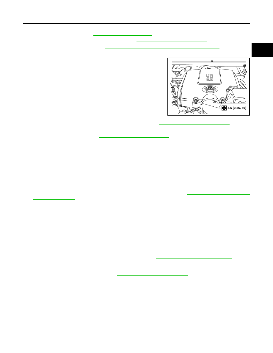
7. Remove the engine room cover, if equipped.

8. Remove the air duct and air cleaner case assembly. Refer to 

EM-25, "Removal and Installation"

.

9. Remove the radiator assembly and hoses. Refer to 

CO-16, "Removal and Installation"

.

10. Remove the drive belt. Refer to 

EM-13, "Removal and Installation"

.

11. Remove the fan blade. Refer to 

CO-19, "Removal and Installation (Crankshaft Driven Type)"

.

12. Disconnect the engine room harness from the fuse box and set it aside.
13. Disconnect the ECM.
14. Disconnect the engine room harness from the engine side and set it aside.
15. Disconnect the engine harness grounds.
16. Disconnect the power steering reservoir tank from the engine and move it aside.
17. Disconnect the power steering oil pump from the engine. Move it aside and secure it using suitable wire or

rope. Refer to 

ST-19, "Removal and Installation"

18. Remove the A/C compressor bolts and set the compressor aside. Refer to 

HA-32, "Removal and Installa-

tion for Compressor"

.

19. Disconnect the brake booster vacuum line.
20. Disconnect the EVAP line.
21. Disconnect the fuel hose at the engine side connection. Refer to 

EM-41, "Removal and Installation"

.

NOTE:

Cap or plug opening(s) to prevent fluid from spilling.

22. Disconnect the heater hoses at the cowl, and install plugs to avoid leakage of engine coolant.

NOTE:

Cap or plug opening(s) to prevent fluid from spilling.

23. Remove the A/T oil level indicator and indicator tube upper bolts.
24. Remove the front final drive assembly (4WD only). Refer to 

DLN-169, "Removal and Installation"

.

NOTE:

Cap or plug opening(s) to prevent fluid from spilling.

25. Remove the exhaust manifolds. Refer to 

EM-30, "Removal and Installation"

.

CAUTION:

Temporarily re-install engine mounts before removing A/T. 

WBIA0795E

EM-86

< UNIT REMOVAL AND INSTALLATION >

ENGINE ASSEMBLY

26. Install the engine slingers into the left bank cylinder head and

right bank cylinder head.

27. Disconnect and remove the crankshaft position sensor (POS).

Refer to 

EM-88, "Exploded View"

.

28. Remove the A/T. Refer to 

TM-206, "Removal and Installation

(2WD)"

 or 

TM-208, "Removal and Installation (4WD)"

.

29. Lift using a hoist and secure the engine in position.
30. Remove the engine assembly from the vehicle, avoid interfer-

ence with the vehicle body.

CAUTION:

• Before and during lifting, always check if any harnesses are left connected.

31. Remove the parts that may restrict installation of the engine to the engine stand.

NOTE:

This procedure is described assuming that you use an engine stand mounting to the surface to which the

transmission mounts.

a. Before removing the drive plate, put a match mark (A) on the

crankshaft and drive plate for alignment during installation. 

b. Remove the drive plate.

• Holding the crankshaft pulley bolt, lock the crankshaft to remove the drive plate bolts.

• Loosen the bolts diagonally.

CAUTION:

• Be careful not to damage the drive plate. Especially

avoid deforming and damaging of the signal plate teeth

(circumference position).

• Place the drive plate with the signal plate surface facing

other than downward.

• Keep magnetic materials away from the signal plate.

CAUTION:

Use an engine stand that has a load capacity [approximately 240kg (529 lb) or more] large enough

for supporting the engine weight.

• If the load capacity of the stand is not adequate, remove the following parts beforehand to

reduce the potential risk of overturning the stand.

- Remove the fuel tube and fuel injector assembly. Refer to 

EM-41, "Removal and Installation"

.

- Remove the intake manifold. Refer to 

EM-26, "Removal and Installation"

.

- Remove the ignition coil. Refer to 

EM-38, "Removal and Installation"

.

- Remove the rocker cover. Refer to 

EM-39, "Removal and Installation"

.

- Other removable brackets.

CAUTION:

Before removing the hanging chains, make sure the engine stand is stable and there is no risk of

overturning.

Engine slinger torque:

45.0 N·m (4.6 kg-m, 33 ft-lb)

WBIA0715E

ALBIA0522ZZ

KBIA2491E

ENGINE ASSEMBLY

EM-87

< UNIT REMOVAL AND INSTALLATION >

C

D

E

F

G

H

I

J

K

L

M

A

EM

N

P

O

32. Remove the generator. Refer to 

CHG-20, "Removal and Installation"

.

33. Remove the engine mounting insulator and bracket using power tool, if necessary.

INSTALLATION

Installation is in the reverse order of removal.

• Tighten engine mounting bracket bolts in numerical order as

shown.

CAUTION:

• When replacing an engine or transmission you must make sure the dowels are installed correctly

during re-assembly.

• Improper alignment caused by missing dowels may cause vibration, oil leaks or breakage of driv-

etrain components.

INSPECTION AFTER INSTALLATION

• Before starting engine, check oil/fluid levels including engine coolant and engine oil. If less than required

quantity, fill to the specified level. Refer to 

GI-15, "Recommended Chemical Products and Sealants"

.

• Use procedure below to check for fuel leakage.

• Turn ignition switch ON (with engine stopped). With fuel pressure applied to fuel piping, check for fuel leak-

age at connection points.

• Start engine. With engine speed increased, check again for fuel leakage at connection points.

• Run engine to check for unusual noise and vibration.

• Warm up engine thoroughly to make sure there is no leakage of fuel, exhaust gas, or any oils/fluids including

engine oil and engine coolant.

• Bleed air from passages in lines and hoses, such as in cooling system.

• After cooling down engine, again check oils/fluids including engine oil and engine coolant. Refill to specified

level, if necessary.

• Summary of the inspection items:

*Power steering fluid, brake fluid, etc.

Engine mounting bracket 
bolts

: 49 N·m (5.0 kg-m, 36 ft-lb)

AWBIA0820ZZ

Item

Before starting engine

Engine running

After engine stopped

Engine coolant

Level

Leakage

Level

Engine oil

Level

Leakage

Level

Transmission/
transaxle fluid

A/T and CVT Models

 Leakage

Level/Leakage

Leakage

M/T Models

Level/Leakage

Leakage

Level/Leakage

Other oils and fluids*

Level

Leakage

Level

Fuel

Leakage

Leakage

Leakage

Exhaust gas

Leakage

EM-88

< UNIT DISASSEMBLY AND ASSEMBLY >

ENGINE UNIT

UNIT DISASSEMBLY AND ASSEMBLY

ENGINE UNIT

Exploded View

INFOID:0000000006179418

1.

Knock sensor sub-harness

2.

 Knock sensor

3.

Cylinder block

4.

Main bearing upper

5.

Top ring

6.

Second ring

7.

Oil ring

8.

Crankshaft key

9.

Piston

10. Connecting rod

11.

Snap ring

12.

Piston pin

13. Connecting rod bearing

14.

Connecting rod bearing cap

15.

Main bearing cap

WBIA0471E


Content   ..  473  474  475  476   ..