Nissan Titan A60. Manual - part 472


  Index      Nissan     Nissan Titan A60 (2011 year) - Service and Repair Manual


Search            


Content   ..  470  471  472  473   ..


Nissan Titan A60. Manual - part 472


OIL SEAL

EM-73

< REMOVAL AND INSTALLATION >

C

D

E

F

G

H

I

J

K

L

M

A

EM

N

P

O

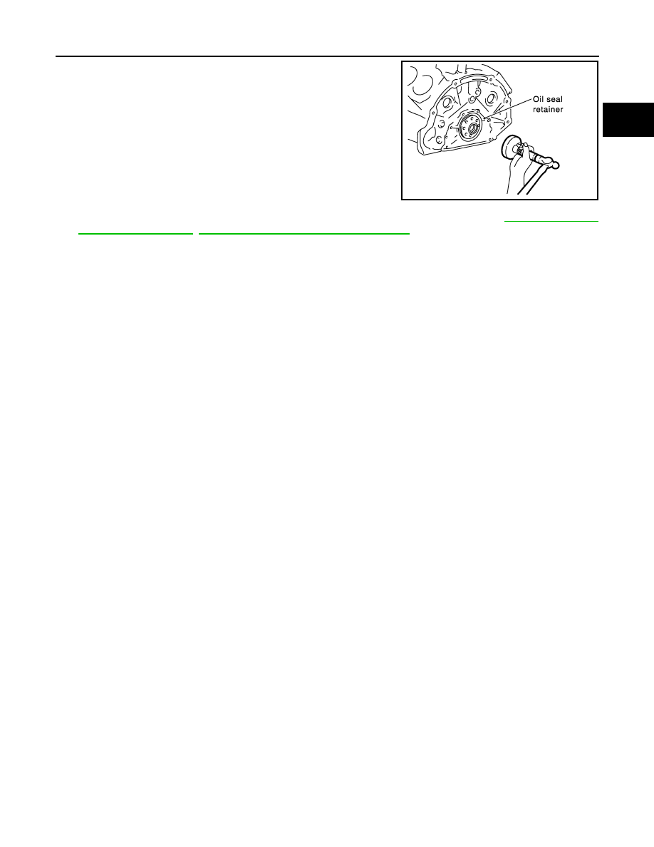
• Press-fit the rear oil seal using suitable tool.

CAUTION:

• Do not damage the crankshaft or cylinder block.

• Press-fit the oil seal straight to avoid causing burrs or

tilting.

• Do not touch grease applied onto the oil seal lip.

• Do not damage or scratch the outer circumference of

the rear oil seal.

• Tap until flattened with the front edge of the oil seal retainer. 

3. Installation of the remaining components is in the reverse order of removal. Refer to 

TM-206, "Removal

and Installation (2WD)"

TM-208, "Removal and Installation (4WD)"

.

CAUTION:

• When replacing an engine or transmission you must make sure the dowels are installed cor-

rectly during re-assembly.

• Improper alignment caused by missing dowels may cause vibration, oil leaks or breakage of

drivetrain components.

WBIA0438E

EM-74

< REMOVAL AND INSTALLATION >

CYLINDER HEAD

CYLINDER HEAD

Exploded View

INFOID:0000000006179411

Removal and Installation

INFOID:0000000006179412

REMOVAL

1. Remove the engine assembly from the vehicle. Refer to 

EM-84, "Removal and Installation"

.

2. Remove the following components and related parts:

• Drive belt auto tensioner, drive belt and idler pulley. Refer to 

EM-14, "Drive Belt Auto Tensioner and Idler

Pulley"

.

• Generator assembly and bracket. Refer to 

CHG-20, "Removal and Installation"

.

• Thermostat housing and hose. Refer to 

CO-23, "Removal and Installation"

.

• Oil pan and oil strainer. Refer to 

EM-33, "Removal and Installation"

• Fuel tube and fuel injector assembly. Refer to 

EM-41, "Removal and Installation"

• Intake manifold. Refer to 

EM-26, "Removal and Installation"

• Rocker cover. Refer to 

EM-39, "Removal and Installation"

.

3. Remove the crankshaft pulley, front cover, oil pump, and timing chain. Refer to 

EM-48, "Removal and

Installation"

.

4. Remove the camshaft sprockets and camshafts. Refer to 

EM-58, "Removal and Installation"

.

5. Remove the cylinder head bolts in reverse of order shown.
6. Remove the cylinder heads.

INSPECTION AFTER REMOVAL

 Cylinder Head Bolts Diameter

1.

Harness bracket

2.

Engine coolant temperature sensor

3.

Washer

4.

Cylinder head gasket (LH)

5.

Cylinder head (RH)

6.

Cylinder head bolt

7.

Cylinder head gasket (RH)

8.

Cylinder head (LH)

KBIA2528E

PBIC0068E

CYLINDER HEAD

EM-75

< REMOVAL AND INSTALLATION >

C

D

E

F

G

H

I

J

K

L

M

A

EM

N

P

O

• Cylinder head bolts are tightened by plastic zone tightening

method. Whenever the size difference between d1 and d2 exceeds

the limit, replace the bolt with a new one. 

• If reduction of diameter appears in a position other than d2, use it

as d2 point.

INSTALLATION

1. Install a new cylinder head gasket.
2. Install the cylinder head. Follow the steps below to tighten the

bolts in the numerical order shown.

CAUTION:

• If cylinder head bolts are re-used, check their diameters

before installation. Follow the "Cylinder Head Bolts Diam-

eter" procedure.

a. Apply engine oil to threads and seating surface of the bolts.

b. Measure the tightening angle using Tool.

CAUTION:

Measure the tightening angle using Tool. Do not measure

visually. 

3. Installation of the remaining components is in the reverse order of removal.

INSPECTION AFTER INSTALLATION

• Before starting engine, check oil/fluid levels including engine coolant and engine oil. If less than required

quantity, fill to the specified level. Refer to 

GI-15, "Recommended Chemical Products and Sealants"

.

• Use procedure below to check for fuel leakage.

• Turn ignition switch ON (with engine stopped). With fuel pressure applied to fuel piping, check for fuel leak-

age at connection points.

• Start engine. With engine speed increased, check again for fuel leakage at connection points.

• Run engine to check for unusual noise and vibration.

• Warm up engine thoroughly to make sure there is no leakage of fuel, exhaust gas, or any oils/fluids including

engine oil and engine coolant.

• Bleed air from passages in lines and hoses, such as in cooling system.

• After cooling down engine, again check oils/fluids including engine oil and engine coolant. Refill to specified

level, if necessary.

• Summary of the inspection items:

Limit (d1 - d2)

: 0.23 mm (0.0091 in)

KBIA0189E

PBIC0068E

Step a : 44.1 N·m (4.5 kg-m, 33 ft-lb) 
Step b : 70

° clockwise

Step c : Loosen in the reverse order of tightening.
Step d : 44.1 N·m (4.5 kg-m, 33 ft-lb)
Step e : 60

° clockwise

Step f

: 60

° clockwise

Tool number

: KV10112100 (BT-8653-A)

WBIA0603E

EM-76

< REMOVAL AND INSTALLATION >

CYLINDER HEAD

*Power steering fluid, brake fluid, etc.

Exploded View

INFOID:0000000006179413

Disassembly and Assembly

INFOID:0000000006179414

DISASSEMBLY

1. Remove the spark plug. Refer to 

EM-16, "Removal and Installation"

.

2. Remove the valve lifter.

• Identify the installation positions, and store them without mixing them up.

Item

Before starting engine

Engine running

After engine stopped

Engine coolant

Level

Leakage

Level

Engine oil

Level

Leakage

Level

Transmission/
transaxle fluid

A/T and CVT Models

 Leakage

Level/Leakage

Leakage

M/T Models

Level/Leakage

Leakage

Level/Leakage

Other oils and fluids*

Level

Leakage

Level

Fuel

Leakage

Leakage

Leakage

Exhaust gas

Leakage

1.

Spark plug

2.

Valve lifter

3.

Valve collet

4.

Valve spring retainer

5.

Valve spring

6.

Valve spring seat

7.

Valve oil seal

8.

Valve guide

9.

Valve seat

10.

Valve (INT)

11. Valve (EXH)

12.

Cylinder head (LH bank)

13.

Spark plug tube

14. Cylinder head (RH bank)

WBIA0470E


Content   ..  470  471  472  473   ..