Nissan Titan A60. Manual - part 96
AV
DIAGNOSIS SYSTEM (NAVI CONTROL UNIT)
AV-209
< SYSTEM DESCRIPTION >
[PREMIUM WITH NAVIGATION]
C
D
E
F
G
H
I
J
K
L
M
B
A
O
P
DIAGNOSIS SYSTEM (NAVI CONTROL UNIT)
Diagnosis Description
INFOID:0000000006166571
DESCRIPTION
• Diagnosis function consists of the self-diagnosis mode performed automatically and the CONFIRMATION/
ADJUSTMENT mode operated manually.
• Self-diagnosis mode checks for connections between the units constituting this system, analyzes each indi-
vidual unit at the same time, and displays the results on the LCD screen.
• CONFIRMATION/ADJUSTMENT mode is used to perform trouble diagnosis that require operation and judg-
ment by an operator (trouble that cannot be automatically judged by the system), to check/change the set
value, and to display the Error History of the navigation system.
Work Flow
INFOID:0000000006166572
ON BOARD SELF-DIAGNOSIS FUNCTION
Diagnosis Item
NOTE:
Make the status that is set by D/N function be shown.
SELF-DIAGNOSIS MODE (DCU)
1. Start the engine.
2. Turn the audio system off.
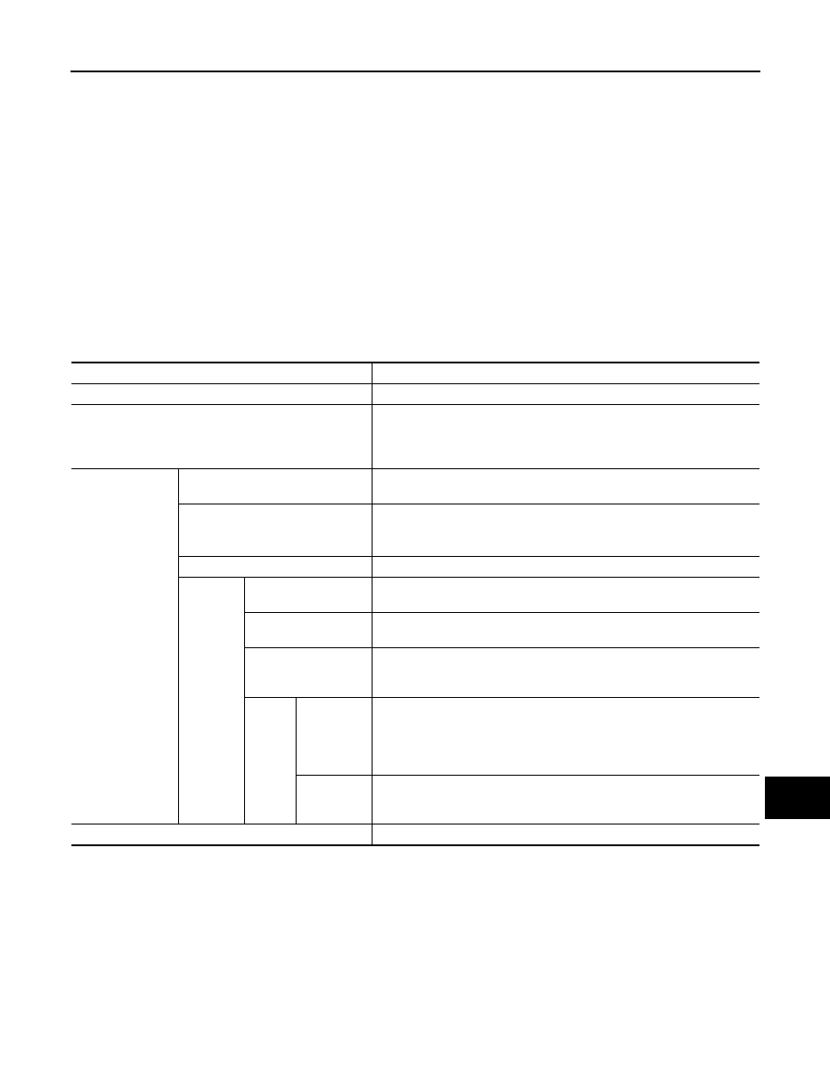
Mode
Description
Self-diagnosis (DCU)
Display control unit diagnosis.
Self-diagnosis (NAVI)
• NAVI Control unit diagnosis (DVD-ROM drive) will not be diagnosed
when no map DVD-ROM is in it.
• Analyzes connection between the NAVI control unit and the GPS anten-
na and operation of each unit.
CONFIRMATION/
ADJUSTMENT
Display diagnosis
On display control unit mode, color tone and shading of the screen can be
checked by the display of a color bar and a gray scale.
Vehicle signals
On display control unit mode, analyzes the following vehicle signals: Vehi-
cle speed signal, light signal
NOTE
, ignition switch signal, and reverse sig-
nal.
Auto Climate Control (if equipped)
A/C self-diagnosis of A/C system.
Navigation
Display diagnosis
On NAVI C/U mode, color tone and shading of the screen can be checked
by the display of a color bar and a gray scale.
Vehicle signals
On NAVI C/U mode, analyzes the following vehicle signals: Vehicle speed
signal, light signal, ignition switch signal, and reverse signal.
Error History
Diagnosis results previously stored in the memory (before turning ignition
switch ON) are displayed in this mode. Time and location when/where the
errors occurred are also displayed.
Naviga-
tion
Speed Cali-
bration
Under ordinary conditions, the navigation system distance measuring func-
tion will automatically compensate for minute decreases in wheel and tire
diameter caused by tire wear or low-pressure. Speed calibration immedi-
ately restores system accuracy in cases such as when distance calibration
is needed because of the use of tire chains in inclement weather.
Steering An-
gle Adjust-
ment
Corrects difference between actual turning angle of a vehicle and turning
angle of the car mark on the display.
CAN DIAG SUPPORT MONITOR
Display status of CAN communication.