Nissan Titan A60. Manual - part 20
ADP-70
< DTC/CIRCUIT DIAGNOSIS >
DOOR MIRROR REMOTE CONTROL SWITCH
Is the inspection result normal?
YES
>> GO TO 6
NO
>> GO TO 2
2.
CHECK HARNESS CONTINUITY
1. Turn ignition switch OFF.
2. Disconnect automatic drive positioner control unit and door mir-
ror remote control switch.
3. Check continuity between automatic drive positioner control unit
connector and door mirror remote control switch connector.
4. Check continuity between automatic drive positioner control unit connector and ground.
Is the inspection result normal?
YES
>> GO TO 3
NO
>> Repair or replace harness.
3.
CHECK DOOR MIRROR REMOTE CONTROL SWITCH GROUND CIRCUIT
Terminals
Mirror switch
Condition
Voltage (V)
(Approx.)
(+)
(–)
Automatic drive
positioner control
unit connector
Terminal
M33
3
Ground
UP
0
Other than above
5
4
LEFT
0
Other than above
5
19
DOWN
0
Other than above
5
20
RIGHT
0
Other than above
5
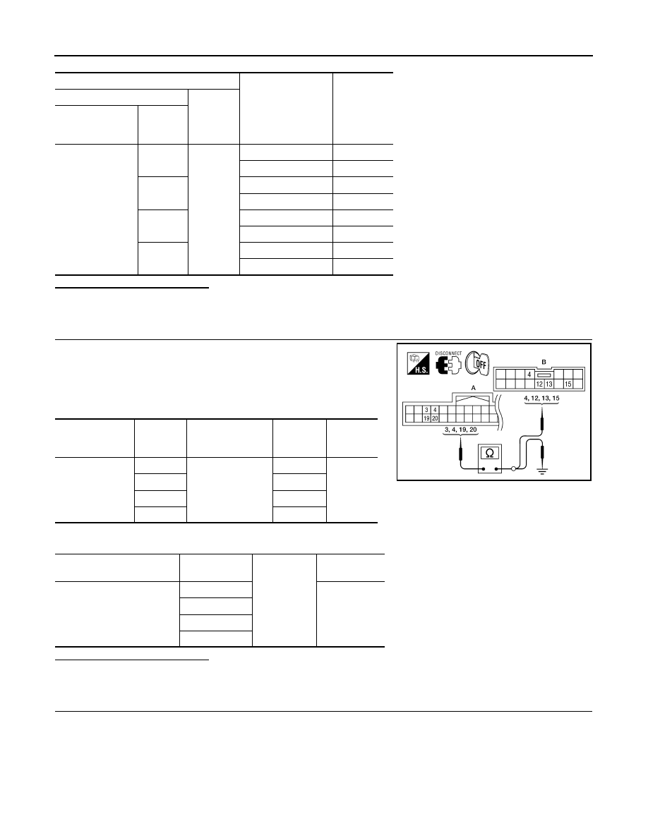
Automatic drive
positioner control
unit connector
Terminal
Door mirror remote
control switch con-
nector
Terminal
Continuity
M33 (A)
3
D10 (B)
15
Yes
4
13
19
12
20
4
Automatic drive positioner
control unit connector
Terminal
Ground
Continuity
M33 (A)
3
No
4
19
20
ALJIA0191ZZ