Nissan Titan A60. Manual - part 16
ADP-54
< DTC/CIRCUIT DIAGNOSIS >
RECLINING SWITCH
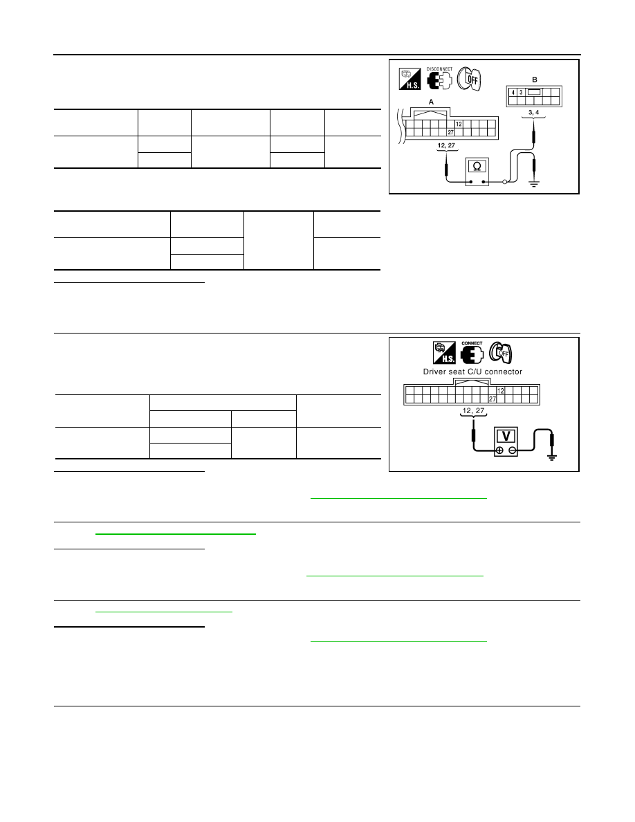
1. Disconnect driver seat control unit and power seat switch LH.
2. Check continuity between driver seat control unit harness con-
nector and power seat switch LH harness connector.
3. Check continuity between driver seat control unit harness con-
nector and ground.
Is the inspection result normal?
YES
>> GO TO 3
NO
>> Repair or replace harness.
3.
CHECK DRIVER SEAT CONTROL UNIT OUTPUT
1. Connect the driver seat control unit.
2. Turn ignition switch OFF.
3. Check voltage between driver seat control unit harness connec-
tor and ground.
Is the inspection result normal?
YES
>> GO TO 4
NO
>> Replace driver seat control unit. Refer to
ADP-148, "Removal and Installation"
4.
CHECK RECLINING SWITCH
ADP-54, "Component Inspection"
.
Is the inspection result normal?
YES
>> GO TO 5
NO
>> Replace power seat switch LH. Refer to
SE-44, "Disassembly and Assembly"
5.
CHECK INTERMITTENT INCIDENT
GI-39, "Intermittent Incident"
Is the inspection result normal?
YES
>> Replace driver seat control unit. Refer to
ADP-148, "Removal and Installation"
NO
>> Repair or replace the malfunctioning part.
Component Inspection
INFOID:0000000006163498
1.
CHECK RECLINING SWITCH
Driver seat control
unit connector
Terminal
Power seat switch
LH connector
Terminal
Continuity
B202 (A)
12
B208 (B)
3
Yes
27
4
Driver seat control unit
connector
Terminal
Ground
Continuity
B202 (A)
12
No
27
ALJIA0310ZZ
Driver seat control
unit connector
Terminals
Voltage (V)
(Approx.)
(+)
(–)
B202
12
Ground
Battery voltage
27
PIIA4580E