Nissan Titan A60. Manual - part 8
ADP-22
< SYSTEM DESCRIPTION >
AUTOMATIC DRIVE POSITIONER SYSTEM
EXIT ASSIST FUNCTION : Component Parts Location
INFOID:0000000006163450
EXIT ASSIST FUNCTION : Component Description
INFOID:0000000006163451
CONTROL UNITS
INPUT PARTS
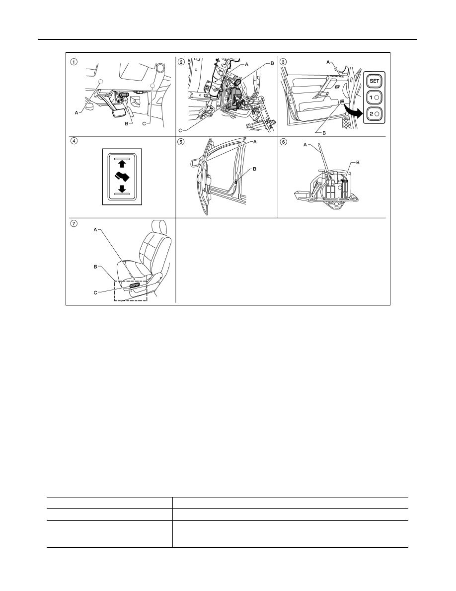
ALJIA0514ZZ
1.
A. Automatic drive positioner control
unit M33, M34
B. Pedal adjusting motor assembly
E109, E110
C. A/T shift selector (column shift)
M68
2.
A. Steering column
B. Key switch and key lock solenoid
M27
C. BCM M18, M19, M20 (view with
instrument panel removed)
3.
A. Door mirror remote control switch
D10
B. Seat memory switch D5
4.
Pedal adjusting switch M96
5.
A. Door mirror LH D4, RH D107
B. Front door switch LH B8
6.
A. A/T selector lever (floor shift)
B. A/T shift selector (park position
switch) M203 (King Cab), M204
(Crew Cab)
7.
A. Sliding motor LH B204 (driver seat
view), reclining motor LH B205, lift-
ing motor (front) B206, lifting motor
(rear) B207
B. Driver seat control unit B202,
B203
C. Power seat switch LH B208
Item
Function
Driver seat control unit
Operates the seat sliding motor for a constant amount.
BCM
Recognizes the following status and transmits it to the driver seat control unit via
CAN communication.
• Front door LH: OPEN/CLOSE