Nissan Quest E52. Manual - part 919


  Index      Nissan     Nissan Quest E52 (2011-2014 year) - Service and Repair Manual


Search            


Content   ..  917  918  919  920   ..


Nissan Quest E52. Manual - part 919


MWI

WASHER LEVEL SWITCH SIGNAL CIRCUIT

MWI-81

< DTC/CIRCUIT DIAGNOSIS >

C

D

E

F

G

H

I

J

K

L

M

B

A

O

P

WASHER LEVEL SWITCH SIGNAL CIRCUIT

Diagnosis Procedure

INFOID:0000000009651519

1.

CHECK WASHER LEVEL SWITCH SIGNAL CIRCUIT

1.

Turn ignition switch OFF.

2.

Disconnect combination meter connector and washer level switch connector.

3.

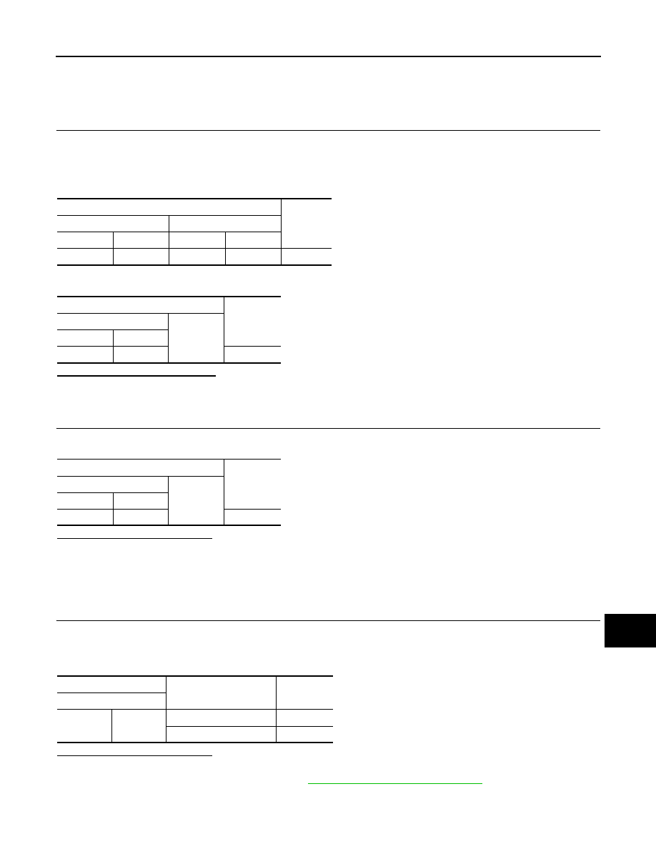
Check continuity between combination meter harness connector and washer level switch harness con-
nector.

4.

Check continuity between combination meter harness connector and ground.

Is the inspection result normal? 

YES

>> GO TO 2.

NO

>> Repair harness or connector.

2.

CHECK WASHER LEVEL SWITCH GROUND CIRCUIT

Check continuity between washer level switch connector and ground.

Is the inspection result normal?

YES

>> INSPECTION END

NO

>> Repair harness or connector.

Component Inspection

INFOID:0000000009651520

1.

CHECK WASHER LEVEL SWITCH

1.

Turn ignition switch OFF.

2.

Disconnect washer level switch connector. 

3.

Check washer level switch.

Is the inspection result normal?

YES

>> INSPECTION END

NO

>> Replace washer level switch. Refer to 

WW-71, "Removal and Installation"

.

Terminals

Continuity

Combination meter

Washer level switch

Connector

Terminal

Connector

Terminal

M34

29

E303

1

Existed

Terminals

Continuity

Combination meter

Ground

Connector

Terminal

M34

29

Not existed

Terminals

Continuity

Washer level switch

Ground

Connector

Terminal

E303

2

Existed

Terminals

Condition

Continuity

Washer level switch

1

2

Washer level switch ON

Existed

Washer level switch OFF

Not existed

MWI-82

< DTC/CIRCUIT DIAGNOSIS >

A/C AUTO AMP. CONNECTION RECOGNITION SIGNAL CIRCUIT

A/C AUTO AMP. CONNECTION RECOGNITION SIGNAL CIRCUIT

Diagnosis Procedure

INFOID:0000000009651521

1.

CHECK A/C AUTO AMP. CONNECTION RECOGNITION SIGNAL

1.

Turn ignition switch ON.

2.

Check voltage between combination meter harness connector and ground.

Is the inspection result normal?

YES

>> INSPECTION END

NO

>> GO TO 2.

2.

CHECK A/C AUTO AMP. CONNECTION RECOGNITION SIGNAL CIRCUIT

1.

Turn ignition switch OFF.

2.

Disconnect combination meter connector and A/C auto amp. connector.

3.

Check continuity between combination meter harness connector and A/C auto amp. harness connector.

4.

Check continuity between combination meter harness connector and ground.

Is the inspection result normal?

YES

>> INSPECTION END

NO

>> Repair harness or connector.

Terminals

Voltage

(Approx.)

(+)

(

)

Combination meter

Ground

Connector

Terminal

M34

19

5 V

Combination meter

A/C auto amp.

Continuity

Connector

Terminal

Connector

terminal

M34

19

M50

20

Existed

Combination meter

Ground

Continuity

Connector

Terminal

M34

19

Not existed

MWI

THE FUEL GAUGE INDICATOR DOES NOT OPERATE

MWI-83

< SYMPTOM DIAGNOSIS >

C

D

E

F

G

H

I

J

K

L

M

B

A

O

P

SYMPTOM DIAGNOSIS

THE FUEL GAUGE INDICATOR DOES NOT OPERATE

Description

INFOID:0000000009651522

Fuel gauge will not indicate from a certain position.

Diagnosis Procedure

INFOID:0000000009651523

1.

CONDUCTING THE COMBINATION METER SELF-DIAGNOSIS MODE

Perform the self-diagnosis mode of combination meter, and then check that the fuel gauge operates normally.
Refer to 

MWI-34, "On Board Diagnosis Function"

Is the inspection result normal?

YES

>> GO TO 2.

NO

>> Replace the combination meter. 

2.

CHECK FLOAT INTERFERENCE

Check that the float arm interferes with or binds to other components in the fuel tank.

Is the inspection result normal?

YES

>> GO TO 3.

NO

>> Repair or replace malfunctioning part.

3.

CHECK FUEL LEVEL SENSOR SIGNAL CIRCUIT

Check the fuel level sensor signal circuit. Refer to 

MWI-77, "Component Function Check"

Is the inspection result normal?

YES

>> Check intermittent incident. Refer to 

GI-42, "Intermittent Incident"

.

NO

>> Repair or replace malfunctioning parts.

MWI-84

< SYMPTOM DIAGNOSIS >

THE METER CONTROL SWITCH IS INOPERATIVE

THE METER CONTROL SWITCH IS INOPERATIVE

Description

INFOID:0000000009651524

If any of the following malfunctions is found for the meter control switch operation.
• All switches are inoperative
• The specified switch cannot be operated

Diagnosis Procedure

INFOID:0000000009651525

1.

CHECK METER CONTROL SWITCH SIGNAL CIRCUIT

Check the meter control switch signal circuit. Refer to 

MWI-73, "Diagnosis Procedure"

Is the inspection result normal?

YES

>> GO TO 2.

NO

>> Repair harness or connector.

2.

CHECK METER CONTROL SWITCH

Perform a unit check for the meter control switch. Refer to 

MWI-73, "Component Inspection"

Is the inspection result normal?

YES

>> Replace combination meter. Refer to 

MWI-93, "Removal and Installation"

.

NG

>> Replace meter control switch. Refer to 

MWI-95, "Removal and Installation"

.


Content   ..  917  918  919  920   ..