Nissan Quest E52. Manual - part 917
MWI
METER CONTROL SWITCH SIGNAL CIRCUIT
MWI-73
< DTC/CIRCUIT DIAGNOSIS >
C
D
E
F
G
H
I
J
K
L
M
B
A
O
P
METER CONTROL SWITCH SIGNAL CIRCUIT
Diagnosis Procedure
INFOID:0000000009651510
1.
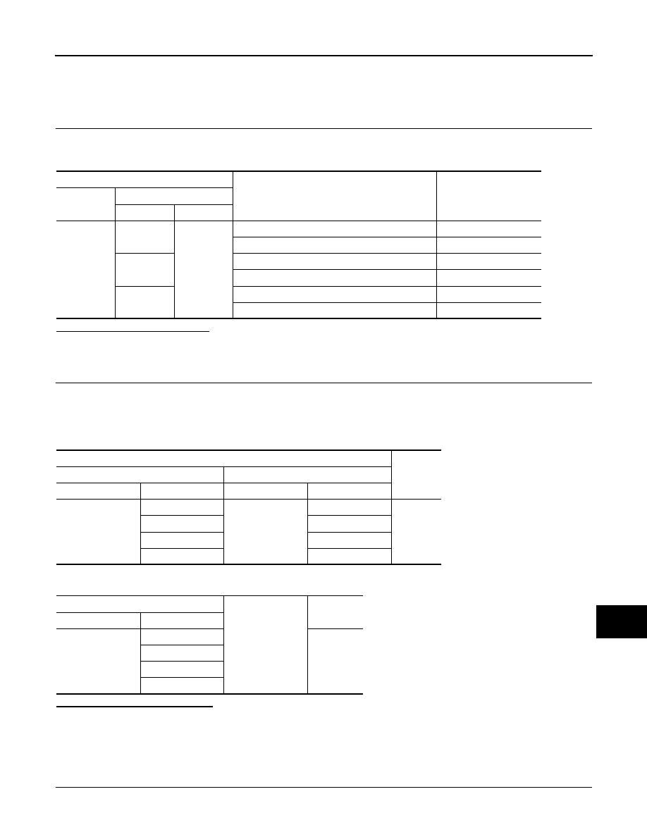
CHECK COMBINATION METER INPUT SIGNAL
1.
Turn ignition switch ON.
2.
Measure voltage between the following terminals of the combination meter.
Is the inspection result normal?
YES
>> INSPECTION END
NO
>> GO TO 2.
2.
CHECK METER CONTROL SWITCH SIGNAL CIRCUIT
1.
Turn ignition switch OFF.
2.
Disconnect combination meter connector and meter control switch connector.
3.
Check continuity between combination meter harness connector and meter control switch harness con-
nector.
4.
Check continuity between combination meter harness connector and ground.
Is the inspection result normal?
YES
>> INSPECTION END
NO
>> Repair harness or connector.
Component Inspection
INFOID:0000000009651511
1.
CHECK METER CONTROL SWITCH
1.
Turn ignition switch OFF.
Combination meter
Condition
Voltage
(Approx.)
Connector
Terminals
(+)
(
−
)
M34
11
10
When enter switch is pressed
0 V
Other than the above
5 V
12
When select switch is pressed
0 V
Other than the above
5 V
8
When trip reset switch is pressed
0 V
Other than the above
5 V
Terminals
Continuity
Combination meter
Meter control switch
Connector
Terminal
Connector
Terminal
M34
8
M54
5
Existed
10
6
11
3
12
4
Combination meter
Ground
Continuity
Connector
Terminal
M34
8
Not existed
10
11
12