Nissan Quest E52. Manual - part 875


  Index      Nissan     Nissan Quest E52 (2011-2014 year) - Service and Repair Manual


Search            


Content   ..  873  874  875  876   ..


Nissan Quest E52. Manual - part 875


OIL COOLER

LU-13

< REMOVAL AND INSTALLATION >

C

D

E

F

G

H

I

J

K

L

M

A

LU

N

P

O

1.

Remove front wheel (RH).

2.

Remove splash guard (RH). Refer to 

EXT-23, "Exploded View"

.

3.

Drain engine coolant from radiator and cylinder block. Refer to 

CO-8, "Draining"

 and 

EM-63, "Setting"

.

NOTE:
Perform this step when removing water pipes.

4.

Remove oil filter. Refer to 

LU-11, "Removal and Installation"

.

CAUTION:

Never spill engine oil on drive belt.

5.

Disconnect water hoses from oil cooler.
• When removing oil cooler only, pinching water hoses near oil cooler to prevent engine coolant from spill-

ing out.

• Remaining engine coolant in piping will come out. Use a tray to collect it.

CAUTION:

• Perform this step when the engine is cold.
• Never spill engine coolant on drive belt.

6.

Remove connector bolt, and remove oil cooler.

CAUTION:

Never spill engine oil to rubber parts such as drive belt.

7.

Remove water hoses if necessary.
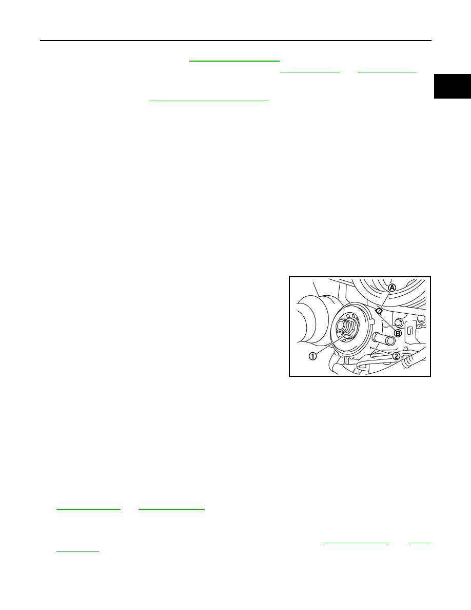
INSTALLATION

CAUTION:

Do not reuse O-rings.
Note the following, and install in the reverse order of removal.
• Check that no foreign objects are adhering to the installation surfaces of oil cooler and oil pan (upper).
• Align cutout (B) on oil cooler (2) with protrusion (A) on oil pan

(upper) side, and tighten connector bolt (1).

Inspection

INFOID:0000000009648848

INSPECTION AFTER REMOVAL

Oil Cooler

Check oil cooler for cracks. Check oil cooler for clogging by blowing through engine coolant inlet. If necessary,
replace oil cooler.

Relief Valve

Inspect relief valve for movement, cracks and breaks by pushing the ball. If replacement is necessary, remove
relief valve by prying it out with a suitable tool. Install a new relief valve in place by tapping it.

INSPECTION AFTER INSTALLATION

1.

Check the engine oil level and the engine coolant level and add engine oil and engine coolant. Refer to

LU-8, "Inspection"

 and 

CO-8, "Inspection"

.

2.

Start the engine, and check there is no leakage of engine oil or engine coolant.

3.

Stop the engine and wait for 10 minutes.

4.

Check the engine oil level and the engine coolant level again. Refer to 

LU-8, "Inspection"

 and 

CO-8,

"Inspection"

.

JPBIA1680ZZ

LU-14

< UNIT DISASSEMBLY AND ASSEMBLY >

OIL PUMP

UNIT DISASSEMBLY AND ASSEMBLY

OIL PUMP

Exploded View

INFOID:0000000009648849

Removal and Installation

INFOID:0000000009648850

REMOVAL

1.

Remove oil pan (lower and upper) and oil strainer. Refer to 

EM-38, "Exploded View"

.

2.

Remove front timing chain case and timing chain (primary). Refer to 

EM-66, "Exploded View"

.

3.

Remove oil pump assembly.

INSTALLATION

Note the following, and install in the reverse order of removal.
• When installing, align crankshaft flat faces with oil pump inner rotor flat faces.

Disassembly and Assembly

INFOID:0000000009648851

DISASSEMBLY

1.

Remove oil pump cover.

2.

Remove oil pump inner rotor and oil pump outer rotor from oil pump body.

3.

After removing regulator valve plug, remove regulator valve spring and regulator valve.

ASSEMBLY

Note the following, and assemble in the reverse order of disassembly.

1.

Oil pump body

2.

Oil pump outer rotor

3.

Oil pump inner rotor

4.

Oil pump cover

5.

Regulator valve plug

6.

Regulator valve spring

7.

Regulator valve

 : N·m (kg-m, ft-lb)

 : N·m (kg-m, in-lb)

 : Should be lubricated with oil.

JPBIA1681GB

OIL PUMP

LU-15

< UNIT DISASSEMBLY AND ASSEMBLY >

C

D

E

F

G

H

I

J

K

L

M

A

LU

N

P

O

• Install oil pump inner rotor with the groove (C) faced to oil pump

cover side (B).

Inspection

INFOID:0000000009648852

INSPECTION AFTER DISASSEMBLY

Oil Pump Clearance

• Measure the clearance with feeler gauge (C).
- Clearance between oil pump outer rotor and oil pump body. [Posi-

tion (B)]

- Tip clearance between oil pump inner rotor and oil pump outer

rotor. [Position (A)]

• Measure the clearance with feeler gauge and straightedge (A).
- Side clearance between oil pump inner rotor and oil pump body.

[Position (C)]

- Side clearance between oil pump outer rotor and oil pump body.

[Position (B)]

• Calculate the clearance between oil pump inner rotor and oil pump body as follows:

OIL PUMP BODY INNER DIAMETER

- Measure the inner diameter of oil pump body with inside microme-

ter. [Position (A)]

OIL PUMP INNER ROTOR OUTER DIAMETER

- Measure the outer diameter of protruded portion of oil pump inner

rotor (1) with micrometer. [Position (B)]

OIL PUMP INNER ROTOR TO OIL PUMP BODY CLEARANCE

- (Clearance) = (Oil pump body inner diameter) – (Oil pump inner rotor outer diameter)

A : Oil pump body side

JPBIA0084ZZ

Standard

: Refer to 

LU-17, "Oil Pump"

.

Standard

: Refer to 

LU-17, "Oil Pump"

.

JPBIA0078ZZ

Standard

: Refer to 

LU-17, "Oil Pump"

.

Standard

: Refer to 

LU-17, "Oil Pump"

.

JPBIA0079ZZ

JPBIA0080ZZ

LU-16

< UNIT DISASSEMBLY AND ASSEMBLY >

OIL PUMP

• If measured/calculated values are out of the standard, replace oil pump assembly.

Regulator Valve Clearance

(Clearance) = (Regulator valve hole diameter) – (Regulator valve
outer diameter)

• If the calculated value is out of the standard, replace oil pump

assembly.

CAUTION:

• Coat regulator valve with engine oil.
• Check that it falls smoothly into valve hole by its own weight.

INSPECTION AFTER INSTALLATION

1.

Check the engine oil level. Refer to 

LU-8, "Inspection"

.

2.

Start the engine, and check that there is no leakage of engine oil.

3.

Stop the engine and wait for 10 minutes.

4.

Check the engine oil level and adjust the level. Refer to 

LU-8, "Inspection"

.

Standard

: Refer to 

LU-17, "Oil Pump"

.

1

: Regulator valve

2

: Oil pump body

Standard

: Refer to 

LU-17, "Regulator Valve"

.

JPBIA0081ZZ


Content   ..  873  874  875  876   ..