Nissan Quest E52. Manual - part 715


  Index      Nissan     Nissan Quest E52 (2011-2014 year) - Service and Repair Manual


Search            


Content   ..  713  714  715  716   ..


Nissan Quest E52. Manual - part 715


A/C UNIT ASSEMBLY

HA-51

< REMOVAL AND INSTALLATION >

C

D

E

F

G

H

J

K

L

M

A

B

HA

N

O

P

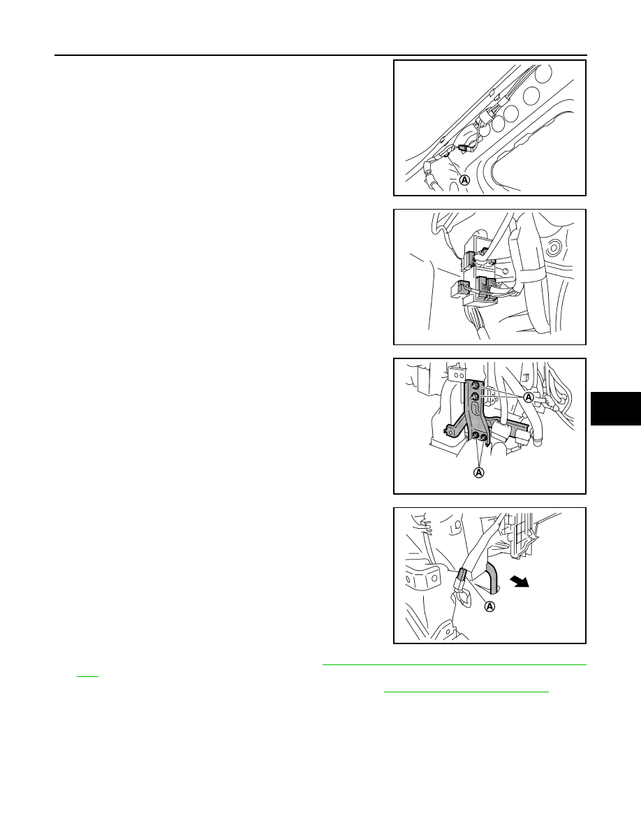
15. Remove harness fixing clip (A), and then disconnect harness

connector.

16. Disconnect junction harness connectors. (Passenger side)

17. Remove mounting nuts (A), and then remove instrument stay.

(LH and RH)

18. Remove harness fixing clip (A).

19. Disconnect drain hose from heater & cooling unit assembly.

20. Disconnect front door harness connector. Refer to 

DLK-432, "DOOR ASSEMBLY : Removal and Installa-

tion"

. (Passenger side)

21. Disconnect diagnosis sensor unit harness connectors. Refer to 

SR-29, "Removal and Installation"

.

NOTE:
Remove all of harness connectors and clips necessary to allow steering member to be moved. Move main
harness aside and secure work space so that steering member can be easily moved.

22. Perform the following operation to move steering member (1).

• Remove steering member mounting bolts (A) from the vehicle.
• Remove steering member mounting bolts (B) and harness fixing clip (C) from heater & cooling unit

assembly

JMIIA1828ZZ

JMIIA1829ZZ

JMIIA1830ZZ

JMIIA1831ZZ

HA-52

< REMOVAL AND INSTALLATION >

A/C UNIT ASSEMBLY

• Remove steering member mounting bolt (C) from blower unit assembly

23. Move steering member to secure work space as shown in the

figure.

24. Remove front A/C unit assembly from the vehicle.
25. Separate blower unit assembly and heater & cooling unit assembly.

INSTALLATION

Note the following items, and then install in the reverse order of removal.

CAUTION:

• Replace O-rings with new ones. Then apply compressor oil to them when installing.
• Check for leakages when recharging refrigerant. Refer to 

HA-18, "Leak Test"

.

NOTE:
Refer to 

CO-9, "Refilling"

 when filling radiator with engine coolant.

EVAPORATOR

EVAPORATOR : Removal and Installation

INFOID:0000000009651594

CAUTION:

Perform lubricant return operation before each refrigeration system disassembly. However, if a large
amount of refrigerant or lubricant is detected, never perform lubricant return operation. Refer to 

HA-

22, "Perform Lubricant Return Operation"

.

REMOVAL

JMIIA1832ZZ

JMIIA1833ZZ

A/C UNIT ASSEMBLY

HA-53

< REMOVAL AND INSTALLATION >

C

D

E

F

G

H

J

K

L

M

A

B

HA

N

O

P

1.

Use a refrigerant collecting equipment (for HFC-134a) to discharge the refrigerant. Refer to 

HA-20, "Recy-

cle Refrigerant"

.

2.

Remove front A/C unit assembly. Refer to 

HA-49, "HEATER & COOLING UNIT ASSEMBLY : Removal

and Installation"

.

3.

Separate blower unit assembly and heater & cooling unit assembly.

4.

Remove foot duct RH. Refer to 

VTL-12, "FOOT DUCT : Removal and Installation"

.

5.

Remove front air mix door motor. (Passenger side)
• Refer to 

HAC-151, "Exploded View"

. (Automatic air conditioning)

• Refer to 

HAC-242, "Exploded View"

. (Manual air conditioning)

6.

Remove fixing screws (A), and then remove heater & cooling
unit case cover (1) and filter cover (2) from heater & cooling unit
assembly as a set.

7.

Pull out evaporator assembly (2) toward heater & cooling unit
assembly (1) to remove.

8.

Remove intake sensor from evaporator assembly. Refer to 

HA-47, "Exploded View"

.

9.

Remove mounting bolts, and  then remove evaporator pipe and expansion valve from evaporator assem-
bly as a set. Refer to 

HA-47, "Exploded View"

.

CAUTION:

Cap or wrap the joint of the evaporator, evaporator pipe, and expansion valve with suitable mate-
rial such as vinyl tape to avoid the entry of air.

INSTALLATION

Note the following items, and then install in the reverse order of removal.

CAUTION:

• Replace O-rings with new ones. Then apply compressor oil to them when installing.
• When install the intake sensor, set the same position before replacement.
• Never rotate the bracket insertion part when removing and installing the intake sensor.
• Perform lubricant adjusting procedure after installing new evaporator. Refer to 

HA-22, "Lubricant

Adjusting Procedure for Components Replacement Except Compressor"

.

EVAPORATOR PIPE ASSEMBLY

EVAPORATOR PIPE ASSEMBLY : Removal and Installation

INFOID:0000000009651595

CAUTION:

Perform lubricant return operation before each refrigeration system disassembly. However, if a large
amount of refrigerant or lubricant is detected, never perform lubricant return operation. Refer to 

HA-

22, "Perform Lubricant Return Operation"

.

REMOVAL

JMIIA1834ZZ

JMIIA1835ZZ

HA-54

< REMOVAL AND INSTALLATION >

A/C UNIT ASSEMBLY

1.

Use a refrigerant collecting equipment (for HFC-134a) to discharge the refrigerant. Refer to 

HA-20, "Recy-

cle Refrigerant"

.

2.

Remove evaporator assembly. Refer to 

HA-52, "EVAPORATOR : Removal and Installation"

.

3.

Remove mounting bolts, and then remove expansion valve from evaporator assembly. Refer to 

HA-47,

"Exploded View"

.

4.

Remove mounting bolts, and then remove evaporator pipe assembly from evaporator assembly. Refer to

HA-47, "Exploded View"

.

CAUTION:

Cap or wrap the joint of expansion valve, evaporator pipe assembly, and evaporator with suitable
material such as vinyl tape to avoid the entry of air.

INSTALLATION

Note the following items, and then install in the reverse order of removal.

CAUTION:

• Replace O-rings with new ones. Then apply compressor oil to them when installing.
• Check for leakages when recharging refrigerant. Refer to 

HA-18, "Leak Test"

.

HEATER CORE

HEATER CORE : Removal and Installation

INFOID:0000000009651596

CAUTION:

Perform lubricant return operation before each refrigeration system disassembly. However, if a large
amount of refrigerant or lubricant is detected, never perform lubricant return operation. Refer to 

HA-

22, "Perform Lubricant Return Operation"

.

REMOVAL

1.

Use a refrigerant collecting equipment (for HFC-134a) to discharge the refrigerant. Refer to 

HA-20, "Recy-

cle Refrigerant"

.

2.

Drain engine coolant from cooling system. Refer to 

CO-8, "Draining"

.

3.

Remove front A/C unit assembly. Refer to 

HA-49, "HEATER & COOLING UNIT ASSEMBLY : Removal

and Installation"

.

4.

Separate blower unit assembly and heater & cooling unit assembly.

5.

Remove heater pipe grommet. Refer to 

HA-47, "Exploded View"

.

6.

Remove fixing screw (A), and then remove fixing pawls.

7.

Remove heater pipe support from heater & cooling unit assembly.

8.

Remove fixing screws (A), and then remove heater pipe cover.

: Pawl

JMIIA1836ZZ

JMIIA1837ZZ


Content   ..  713  714  715  716   ..