Nissan Quest E52. Manual - part 713
CONDENSER
HA-43
< REMOVAL AND INSTALLATION >
C
D
E
F
G
H
J
K
L
M
A
B
HA
N
O
P
CONDENSER
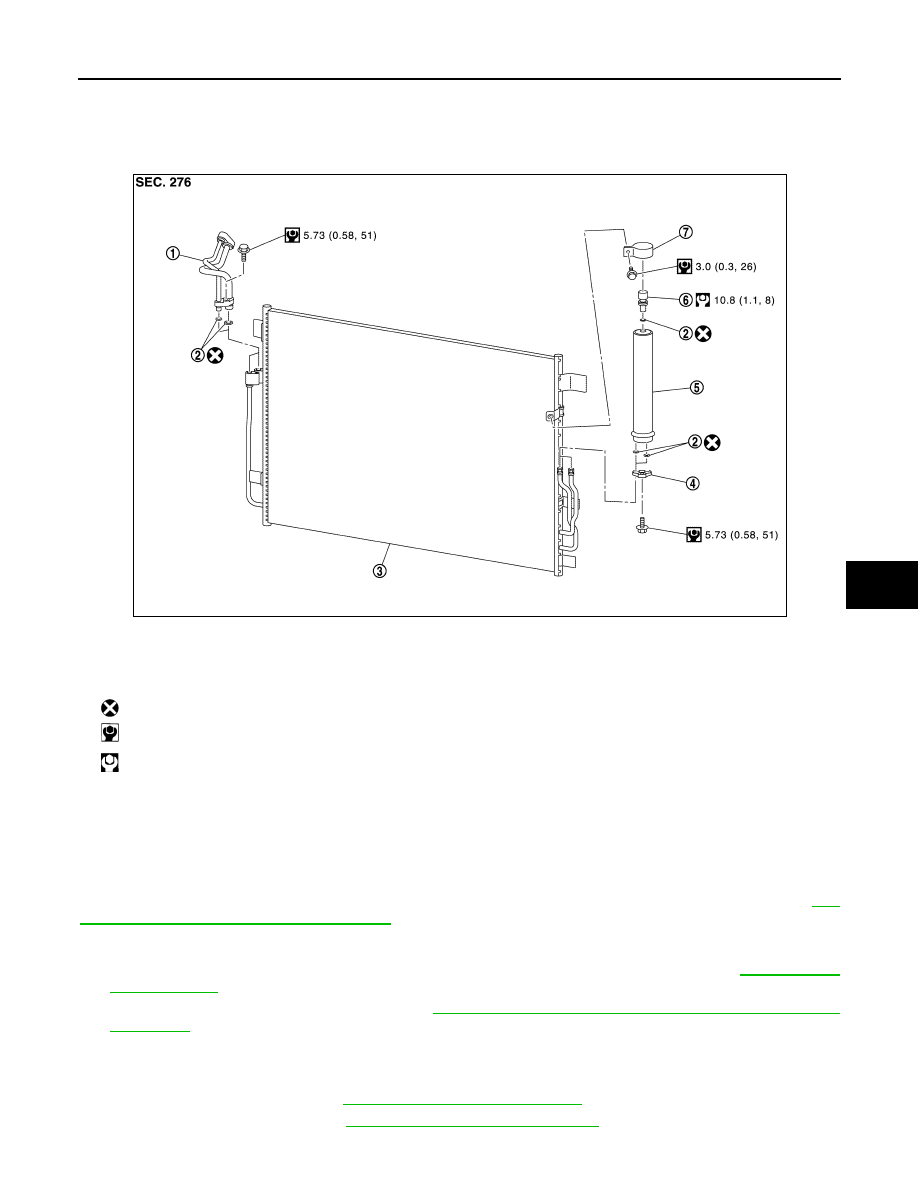
Exploded View
INFOID:0000000009651587
CONDENSER
CONDENSER : Removal and Installation
INFOID:0000000009651588
CAUTION:
Perform lubricant return operation before each refrigeration system disassembly. However, if a large
amount of refrigerant or lubricant is detected, never perform lubricant return operation. Refer to
22, "Perform Lubricant Return Operation"
REMOVAL
1.
Use a refrigerant collecting equipment (for HFC-134a) to discharge the refrigerant. Refer to
2.
Remove condenser pipe assembly. Refer to
HA-44, "CONDENSER PIPE ASSEMBLY : Removal and
.
CAUTION:
Cap or wrap the joint of the condenser pipe assembly and condenser with suitable material such
as vinyl tape to avoid the entry of air.
3.
Remove horn assembly. Refer to
HRN-6, "Removal and Installation"
.
4.
Remove air guide upper. Refer to
DLK-428, "Removal and Installation"
.
1.
Condenser pipe assembly
2.
O-ring
3.
Condenser
4.
Bracket
5.
Liquid tank
6.
Refrigerant pressure sensor
7.
Liquid tank bracket
: Always replace after every disassembly.
: N·m (kg-m, in-lb)
: N·m (kg-m, ft-lb)
JMIIA1839GB