Nissan Quest E52. Manual - part 671
FAX-12
< REMOVAL AND INSTALLATION >
FRONT DRIVE SHAFT BOOT
FRONT DRIVE SHAFT BOOT
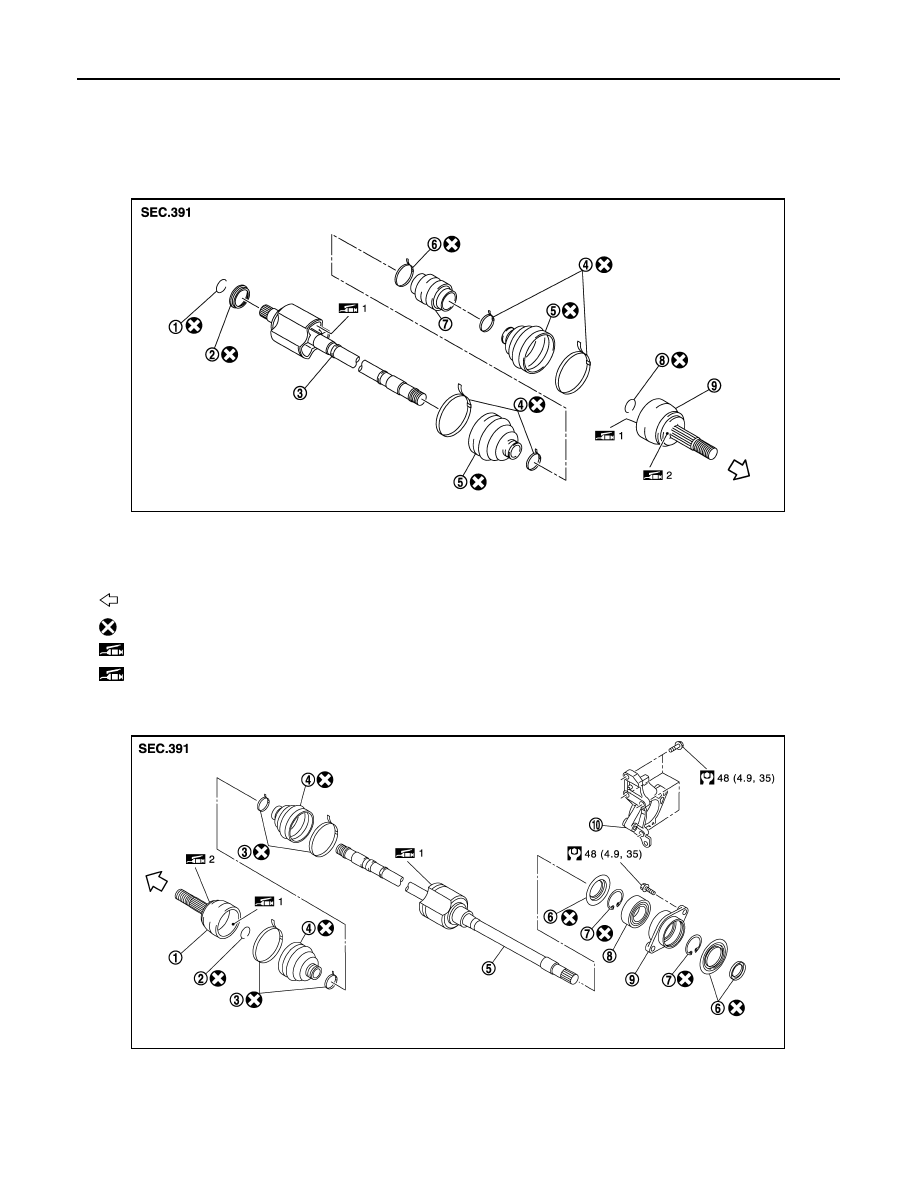
Exploded View
INFOID:0000000009651667
LEFT SIDE
RIGHT SIDE
1.
Circular clip
2.
Dust shield
3.
Housing assembly
4.
Boot band
5.
Boot
6.
Damper band
7.
Dynamic damper
8.
Circular clip
9.
Joint sub-assembly
: Wheel side
: Always replace after every disassembly.
1: Fill NISSAN Genuine grease or equivalent.
2: Apply paste [service parts (440037S000)].
JPDIF0242ZZ
1.
Joint sub-assembly
2.
Circular clip
3.
Boot band
4.
Boot
5.
Housing assembly
6.
Dust shield
7.
Snap ring
8.
Support bearing
9.
Bearing housing
10. Support bearing bracket
JSDIA2706GB