Nissan Quest E52. Manual - part 593


  Index      Nissan     Nissan Quest E52 (2011-2014 year) - Service and Repair Manual


Search            


Content   ..  591  592  593  594   ..


Nissan Quest E52. Manual - part 593


CYLINDER BLOCK

EM-121

< UNIT DISASSEMBLY AND ASSEMBLY >

[VQ35DE]

C

D

E

F

G

H

I

J

K

L

M

A

EM

N

P

O

• Install main bearings (3) to cylinder block (1) and main bearing

caps (2), and main bearing cap bolts with main bearing beam to
the specified torque. Refer to 

EM-105, "Disassembly and Assem-

bly"

 for the tightening procedure.

• Measure the inner diameter of main bearing with a bore gauge.
(Oil clearance) = (Main bearing inner diameter) – (Crankshaft main
journal diameter)

• If the calculated value exceeds the limit, select proper main bear-

ing according to main bearing inner diameter and crankshaft main
journal diameter to obtain the specified bearing oil clearance.
Refer to 

EM-125, "Main Bearing"

.

Method of Using Plastigage

• Remove engine oil and dust on crankshaft journal and the surfaces of each bearing completely. 
• Cut a plastigage slightly shorter than the bearing width, and place it in crankshaft axial direction, avoiding oil

holes.

• Install main bearing to cylinder block and main bearing caps, and tighten main bearing cap bolts with main

bearing beam to the specified torque. Refer to 

EM-105, "Disassembly and Assembly"

 for the tightening pro-

cedure.

CAUTION:

Never rotate crankshaft.

• Remove main bearing caps and bearings, and using the scale on

the plastigage bag, measure the plastigage width. 
NOTE:
The procedure when the measured value exceeds the limit is
same as that described in the “Method by Calculation”.

MAIN BEARING CRUSH HEIGHT

• When main bearing cap is removed after being tightened to the

specified torque with main bearings (1) installed, the tip end of
bearing must protrude. Refer to 

EM-105, "Disassembly and

Assembly"

 for the tightening procedure.

• If the standard is not met, replace main bearings.

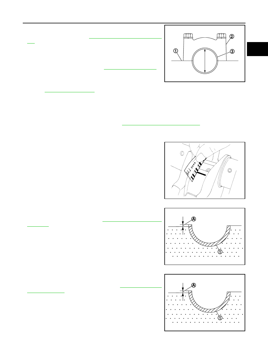
CONNECTING ROD BEARING CRUSH HEIGHT

• When connecting rod bearing cap is removed after being tightened

to the specified torque with connecting rod bearings (1) installed,
the tip end of bearing must protrude. Refer to 

EM-105, "Disassem-

bly and Assembly"

 for the tightening procedure.

• If the standard is not met, replace connecting rod bearings.

Standard and limit

: Refer to 

EM-136, "Main Bearing"

.

JPBIA0232ZZ

JPBIA0231ZZ

A

: Crush height

Standard

: There must be crush height.

JPBIA0233ZZ

A

: Crush height

Standard

: There must be crush height.

JPBIA0233ZZ

EM-122

< UNIT DISASSEMBLY AND ASSEMBLY >

[VQ35DE]

CYLINDER BLOCK

MAIN BEARING CAP BOLT OUTER DIAMETER

• Measure the outer diameters (c), (d) at two positions as shown in

the figure.

• If reduction appears in (a) range, regard it (c).

• If it exceeds the limit (large difference in dimensions), replace main

bearing cap bolt with new one.

CONNECTING ROD BOLT OUTER DIAMETER

• Measure the outer diameter (d) at position shown in the figure.
• If the reduction appears in a position other than (d), regard it as (d).

• When (d) exceeds the limit (when it becomes thinner), replace

connecting rod bolt with new one.

DRIVE PLATE

• Check drive plate and signal plate (A) for deformation or damage.

CAUTION:

• Never disassemble drive plate.
• Never place drive plate with signal plate facing down.
• When handling signal plate, take care not to damage or

scratch it. 

• Handle signal plate in a manner that prevents it from becom-

ing magnetized.

• If anything is found, replace drive plate.

OIL JET

• Check nozzle for deformation and damage.
• Blow compressed air from nozzle, and check for clogs.
• If it is not satisfied, clean or replace oil jet.

OIL JET RELIEF VALVE

• Using a clean plastic stick, press check valve in oil jet relief valve.

Check that valve moves smoothly with proper reaction force.

• If it is not satisfied, replace oil jet relief valve.

a

: 20 mm (0.79 in)

b

: 30 mm (1.18 in)

e

: 10 mm (0.39 in)

Limit [(d) – (c)]

: 0.11 mm (0.0043 in)

JPBIA0234ZZ

Standard 

: 7.90 - 8.00 mm (0.3110 - 0.3150 in)

Limit

: 7.75 mm (0.3051 in)

PBIC0912E

:Engine front

JPBIA0375ZZ

EMU0468D

HOW TO SELECT PISTON AND BEARING

EM-123

< UNIT DISASSEMBLY AND ASSEMBLY >

[VQ35DE]

C

D

E

F

G

H

I

J

K

L

M

A

EM

N

P

O

HOW TO SELECT PISTON AND BEARING

Description

INFOID:0000000009652801

 *: For the service parts, the grade for fitting cannot be selected between piston pin and connecting rod. (Only “0” grade is available.) The
information at the shipment from the plant is described as a reference.

• The identification grade stamped on each part is the grade for the dimension measured in new condition.

This grade cannot apply to reused parts.

• For reused or repaired parts, measure the dimension accurately. Determine the grade by comparing the

measurement with the values of each selection table.

• For details of the measurement method of each part, the reuse standards and the selection method of the

selective fitting parts, refer to the text.

Piston

INFOID:0000000009652802

WHEN NEW CYLINDER BLOCK IS USED

Check the cylinder bore grade (“1”, “2” or “3”) on rear side of cylinder
block, and select piston of the same grade.
NOTE:
Piston is available with piston pin as a set for the service part. (Only
“0” grade piston pin is available.)

WHEN NEW CYLINDER BLOCK IS REUSED

1.

Measure the cylinder bore inner diameter. Refer to 

EM-113, "Inspection"

.

2.

Determine the bore grade by comparing the measurement with the values under the cylinder bore inner
diameter of the “PISTON SELECTION TABLE”.

Selection points

Selection parts

Selection items

Selection methods

Between cylinder block and 
crankshaft

Main bearing

Main bearing grade
(bearing thickness)

Determined by match of cylin-
der block bearing housing 
grade (inner diameter of hous-
ing) and crankshaft journal 
grade (outer diameter of jour-
nal)

Between crankshaft and con-
necting rod

Connecting rod bearing

Connecting rod bearing grade 
(bearing thickness)

Combining service grades for 
connecting rod big end diame-
ter and crankshaft pin outer di-
ameter determine connecting 
rod bearing selection.

Between cylinder block and pis-
ton

Piston and piston pin assembly
(Piston is available together 
with piston pin as assembly.)

Piston grade
(piston skirt diameter)

Piston grade = cylinder bore 
grade (inner diameter of bore)

Between piston and connecting 
rod*

SEM756G

EM-124

< UNIT DISASSEMBLY AND ASSEMBLY >

[VQ35DE]

HOW TO SELECT PISTON AND BEARING

3.

Select piston of the same grade.

PISTON SELECTION TABLE

Unit: mm (in)

NOTE:
• Piston is available together with piston pin as assembly.
• Piston pin (piston pin hole) grade is provided only for the parts installed at the plant. For service parts, no pis-

ton pin grades can be selected. (Only “0” grade is available.)

• No second grade mark is available on piston.

Connecting Rod Bearing

INFOID:0000000009652803

WHEN NEW CONNECTING ROD AND CRANKSHAFT ARE USED

• Check pin diameter grade (“0”, “1” or “2”) on front of crankshaft,

and select connecting rod bearing of the same grade. 

NOTE:
There is no grading for connecting rod big end diameter.

WHEN CONNECTING ROD AND CRANKSHAFT ARE REUSED

1.

Measure the connecting rod big end diameter. Refer to 

EM-113, "Inspection"

.

2.

Check that the connecting rod big end diameter is within the standard value.

3.

Measure the crankshaft pin journal diameter. Refer to 

EM-113, "Inspection"

.

4.

Determine the grade of crankshaft pin diameter grade by corresponding to the measured dimension in
“Crankshaft pin journal diameter” column of “CONNECTING ROD BEARING SELECTION TABLE”.

5.

Select connecting rod bearing of the same grade.

CONNECTING ROD BEARING SELECTION TABLE

Unit: mm (in)

A

: Piston grade number

B

: Front mark

C

: Piston pin grade number

D

: Identification code

JPBIA2199ZZ

Grade

1

2

3

Cylinder bore inner diameter

95.500 - 95.510

(3.7598 - 3.7602)

95.510 - 95.520

(3.7602 - 3.7606)

95.520 - 95.530

(3.7606 - 3.7610)

Piston skirt diameter

95.480 - 95.490

(3.7590 - 3.7594)

95.490 - 95.500

(3.7594 - 3.7598)

95.500 - 95.510

(3.7598 - 3.7602)

A

: Journal diameter grade No. 1

B

: Journal diameter grade No. 2

C

: Journal diameter grade No. 3

D

: Journal diameter grade No. 4

E

: Pin diameter grade No. 1

F

: Pin diameter grade No. 2

G

: Pin diameter grade No. 3

H

: Pin diameter grade No. 4

I

: Pin diameter grade No. 5

J

: Pin diameter grade No. 6

K

: Identification

JPBIA0269ZZ

Connecting rod big end diameter

55.000 - 55.013 (2.1654 - 2.1659)


Content   ..  591  592  593  594   ..