Nissan Quest E52. Manual - part 587


  Index      Nissan     Nissan Quest E52 (2011-2014 year) - Service and Repair Manual


Search            


Content   ..  585  586  587  588   ..


Nissan Quest E52. Manual - part 587


CYLINDER HEAD

EM-97

< UNIT DISASSEMBLY AND ASSEMBLY >

[VQ35DE]

C

D

E

F

G

H

I

J

K

L

M

A

EM

N

P

O

Disassembly and Assembly

INFOID:0000000009652796

DISASSEMBLY

1.

Remove spark plug with spark plug wrench (commercial service tool).

2.

Remove valve lifter.
• Identify installation positions, and store them without mixing them up.

3.

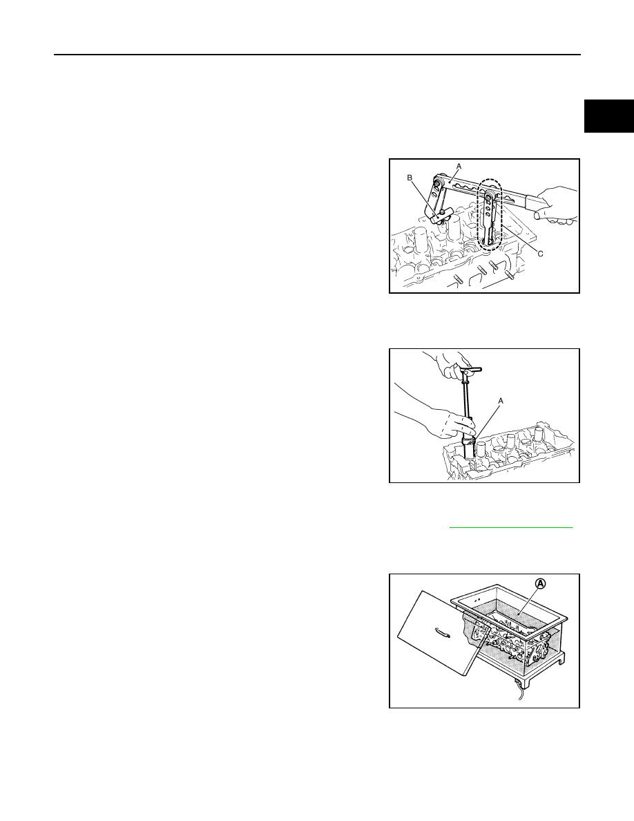
Remove valve collet.
• Compress valve spring with the valve spring compressor [SST:

KV10116200 (J-26336-A)] (A), the attachment [SST:
KV10115900 (J-26336-20)] (C) and the adapter [SST:
KV10109220 ( — )] (B). Remove valve collet with a magnet
hand.

CAUTION:

When working, take care not to damage valve lifter holes.

4.

Remove valve spring retainer, valve spring and valve spring seat.

5.

Push valve stem to combustion chamber side, and remove valve.
• Identify installation positions, and store them without mixing them up.

6.

Remove valve oil seal with the valve oil seal puller [SST:
KV10107902 (J-38959)] (A).

7.

Remove valve seat, if valve seat must be replaced.
• Bore out old seat until it collapses. Boring should not continue beyond the bottom face of the seat

recess in cylinder head. Set the machine depth stop to ensure this. Refer to 

EM-131, "Cylinder Head"

.

CAUTION:

Prevent to scratch cylinder head by excessive boring.

8.

Remove valve guide, if valve guide must be replaced.

a.

To remove valve guide, heat cylinder head to 110 to 130

°

C (230

to 266

°

F) by soaking in heated oil (A).

JPBIA0180ZZ

JPBIA0177ZZ

JPBIA0184ZZ

EM-98

< UNIT DISASSEMBLY AND ASSEMBLY >

[VQ35DE]

CYLINDER HEAD

b.

Drive out valve guide with a press [under a 20 kN (2 ton, 2.2 US
ton, 2.0 lmp ton) pressure] or a hammer and the valve guide drift
(commercial service tool).

WARNING:

Cylinder head contains heat. When working, wear protec-
tive equipment to avoid getting burned.

9.

Remove spark plug tube if necessary.
• Using a pliers, pull spark plug tube out of cylinder head. 

CAUTION:

• Take care not to damage cylinder head.
• Once removed, spark plug tube will be deformed and cannot be reused. Never remove it unless

absolutely necessary.

ASSEMBLY

1.

If valve guide is removed in step 8 (DISASSEMBLY), install it. 
Replace with oversized [0.2 mm (0.008 in)] valve guide.

a.

Using the valve guide reamer (commercial service tool) (A),
ream cylinder head valve guide hole.

b.

Heat cylinder head to 110 to 130

°

C (230 to 266

°

F) by soaking in

heated oil (A).

c.

Using the valve guide drift (commercial service tool), press valve
guide from camshaft side to the dimensions as in the figure.

WARNING:

Cylinder head contains heat. When working, wear protec-
tive equipment to avoid getting burned.

SEM931C

Valve guide hole diameter (for service parts):

Intake and exhaust

: Refer to 

EM-131, "Cylinder Head"

.

JPBIA0185ZZ

JPBIA0184ZZ

Projection (A)

Intake and exhaust

: Refer to 

EM-131, "Cylinder Head"

.

JPBIA0186ZZ

CYLINDER HEAD

EM-99

< UNIT DISASSEMBLY AND ASSEMBLY >

[VQ35DE]

C

D

E

F

G

H

I

J

K

L

M

A

EM

N

P

O

d.

Using the valve guide reamer (commercial service tool) (A),
apply reamer finish to valve guide.

2.

If valve seat is removed in step 7 (DISASSEMBLY), install it. 
Replace with oversize [0.5 mm (0.020 in)] valve seat.

a.

Ream cylinder head recess diameter (a) for service valve seat.

• Be sure to ream in circles concentric to valve guide center.

This will enable valve to fit correctly.

b.

Heat cylinder head to 110 to 130

°

C (230 to 266

°

F) by soaking in

heated oil (A).

c.

Provide valve seats cooled well with dry ice. Force fit valve seat into cylinder head.

WARNING:

Cylinder head contains heat. When working, wear protective equipment to avoid getting burned.

CAUTION:

Avoid directly touching cold valve seats.

d.

Using the valve seat cutter set (commercial service tool) or valve
seat grinder, finish seat to the specified dimensions. Refer to

EM-131, "Cylinder Head"

.

CAUTION:

When using the valve seat cutter, firmly grip cutter handle
with both hands. Then, press on the contacting surface all
around the circumference to cut in a single drive. Improper
pressure on with cutter or cutting many different times may
result in stage valve seat. 

e.

Using compound, grind to adjust valve fitting. 

f.

Check again for normal contact. Refer to 

EM-101, "Inspection"

.

3.

Install new valve oil seals as follows:

Standard

: Refer to 

EM-131, 

"Cylinder Head"

.

(Intake and exhaust)

JPBIA0185ZZ

Oversize

: Refer to 

EM-131, 

"Cylinder Head"

.

(Intake and exhaust)

JPBIA0188ZZ

JPBIA0184ZZ

SEM934C

EM-100

< UNIT DISASSEMBLY AND ASSEMBLY >

[VQ35DE]

CYLINDER HEAD

a.

Apply new engine oil on valve oil seal joint and seal lip.

b.

Install with the valve oil seal drift [SST: KV10115600 (J-38958)]
(A) press fit valve seal to height (b) shown in the figure.
NOTE:
Dimension: Height measured before valve spring seat installa-
tion.

4.

Install valve spring seat.

5.

Install valve.
• Install it in the original position.

NOTE:
Larger diameter valves are for intake side.

6.

Install valve spring (uneven pitch type).
• Install narrow pitch end (paint mark) to cylinder head side

(valve spring seat side).

7.

Install valve spring retainer.

8.

Install valve collet.
• Compress valve spring with the valve spring compressor [SST:

KV10116200 (J-26336-A)] (A), the attachment [SST:
KV10115900 (J-26336-20)] (C) and the adapter [SST:
KV10109220 ( — )] (B). Install valve collet with a magnet
hand.

CAUTION:

When working, take care not to damage valve lifter holes.

• Tap valve stem edge lightly with plastic hammer after installa-

tion to check its installed condition.

9.

Install valve lifter.
• Install it in the original position.

10. Install spark plug tube.

• Press-fit spark plug tube as follows:

a.

Remove old liquid gasket adhering to cylinder head mounting hole.

b.

Apply sealant to area within approximately 12 mm (0.47 in) from edge of spark plug tube press-fit side.
Use genuine high strength thread locking sealant or equivalent. Refer to 

GI-22, "Recommended

Chemical Products and Sealants"

.

Intake and exhaust

: 14.3 - 14.9 mm (0.563 - 0.587 in)

JPBIA0178ZZ

A

: Wide pitch

B

: Narrow pitch

C

: Paint mark

: Cylinder head side

Paint mark color: Blue

JPBIA0179ZZ

JPBIA0180ZZ


Content   ..  585  586  587  588   ..