Nissan Quest E52. Manual - part 586
CYLINDER HEAD
EM-93
< UNIT DISASSEMBLY AND ASSEMBLY >
[VQ35DE]
C
D
E
F
G
H
I
J
K
L
M
A
EM
N
P
O
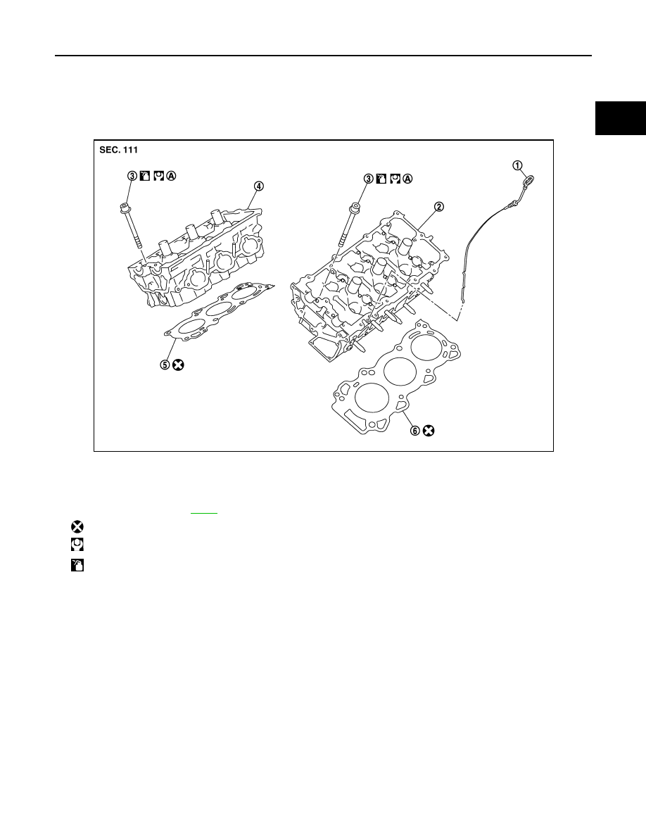
CYLINDER HEAD
Exploded View
INFOID:0000000009652794
REMOVAL
DISASSEMBLY
1.
Oil level gauge
2.
Cylinder head (bank 2)
3.
Cylinder head bolt
4.
Cylinder head (bank 1)
5.
Cylinder head gasket (bank 1)
6.
Cylinder head gasket (bank 2)
A.
Comply with the assembly procedure
when tightening. Refer to
: Always replace after every disassembly.
: N·m (kg-m, ft-lb)
: Should be lubricated with oil.
JPBIA1748ZZ