Nissan Quest E52. Manual - part 554


  Index      Nissan     Nissan Quest E52 (2011-2014 year) - Service and Repair Manual


Search            


Content   ..  552  553  554  555   ..


Nissan Quest E52. Manual - part 554


EC-426

< DTC/CIRCUIT DIAGNOSIS >

[VQ35DE]

FUEL INJECTOR

FUEL INJECTOR

Component Function Check

INFOID:0000000009651286

1.

INSPECTION START

Turn ignition switch to START.
Are any cylinders ignited?

YES

>> GO TO 2.

NO

>> Proceed to 

EC-426, "Diagnosis Procedure"

.

2.

CHECK FUEL INJECTOR FUNCTION

With CONSULT

1.

Start engine.

2.

Perform “POWER BALANCE” in “ACTIVE TEST” mode with CONSULT.

3.

Check that each circuit produces a momentary engine speed drop.

Without CONSULT

1.

Start engine.

2.

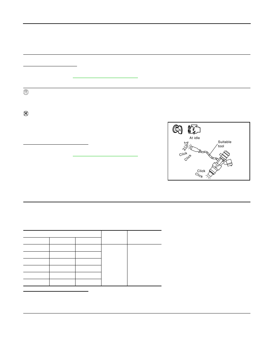
Listen to each fuel injector operating sound.

Is the inspection result normal?

YES

>> INSPECTION END

NO

>> Proceed to 

EC-426, "Diagnosis Procedure"

.

Diagnosis Procedure

INFOID:0000000009651287

1.

CHECK FUEL INJECTOR POWER SUPPLY

1.

Turn ignition switch OFF.

2.

Disconnect fuel injector harness connector.

3.

Turn ignition switch ON.

4.

Check the voltage between fuel injector harness connector and ground.

Is the inspection result normal?

YES

>> GO TO 3.

NO

>> GO TO 2.

2.

CHECK FUEL INJECTOR POWER SUPPLY CIRCUIT

1.

Turn ignition switch OFF.

2.

Disconnect IPDM E/R harness connector.

3.

Check the continuity between fuel injector harness connector and IPDM E/R harness connector.

Clicking sound should be heard.

PBIB3332E

Fuel injector

Ground

Voltage

Cylinder

Connector

Terminal

1

F37

1

Ground

Battery voltage

2

F38

1

3

F39

1

4

F40

1

5

F41

1

6

F42

1

FUEL INJECTOR

EC-427

< DTC/CIRCUIT DIAGNOSIS >

[VQ35DE]

C

D

E

F

G

H

I

J

K

L

M

A

EC

N

P

O

Is the inspection result normal?

YES

>> Perform the trouble diagnosis for power supply circuit.

NO

>> Repair or replace error-detected parts.

3.

CHECK FUEL INJECTOR OUTPUT SIGNAL CIRCUIT FOR OPEN AND SHORT

1.

Turn ignition switch OFF.

2.

Disconnect ECM harness connector.

3.

Check the continuity between fuel injector harness connector and ECM harness connector.

4.

Also check harness for short to ground and short to power.

Is the inspection result normal?

YES

>> GO TO 4.

NO

>> Repair open circuit, short to ground or short to power in harness or connectors.

4.

CHECK FUEL INJECTOR

Check fuel injector. Refer to 

EC-427, "Component Inspection"

.

Is the inspection result normal?

YES

>> GO TO 5.

NO

>> Replace malfunctioning fuel injector. Refer to 

EM-47, "Exploded View"

.

5.

CHECK INTERMITTENT INCIDENT

Check intermittent incident. Refer to 

GI-42, "Intermittent Incident"

.

Is the inspection result normal?

YES

>> Replace IPDM E/R. Refer to 

PCS-36, "Exploded View"

.

NO

>> Repair or replace error-detected parts.

Component Inspection

INFOID:0000000009651288

1.

CHECK FUEL INJECTOR

1.

Turn ignition switch OFF.

2.

Disconnect fuel injector harness connector.

Fuel injector

IPDM E/R

Continuity

Cylinder

Connector

Terminal

Connector

Terminal

1

F37

1

F12

51

Existed

2

F38

1

52

3

F39

1

51

4

F40

1

52

5

F41

1

51

6

F42

1

52

Fuel injector

ECM

Continuity

Cylinder

Connector

Terminal

Connector

Terminal

1

F37

2

F7

33

Existed

2

F38

2

44

3

F39

2

48

4

F40

2

47

5

F41

2

46

6

F42

2

45

EC-428

< DTC/CIRCUIT DIAGNOSIS >

[VQ35DE]

FUEL INJECTOR

3.

Check resistance between fuel injector terminals as per the fol-
lowing.

Is the inspection result normal?

YES

>> INSPECTION END

NO

>> Replace malfunctioning fuel injector. Refer to 

EM-47,

"Exploded View"

.

Terminals

Resistance

1 and 2

11.1 - 14.5 

 [at 10 - 60

°

C (50 - 140

°

F)]

PBIB1727E

FUEL PUMP

EC-429

< DTC/CIRCUIT DIAGNOSIS >

[VQ35DE]

C

D

E

F

G

H

I

J

K

L

M

A

EC

N

P

O

FUEL PUMP

Component Function Check

INFOID:0000000009651289

1.

CHECK FUEL PUMP FUNCTION

1.

Turn ignition switch ON.

2.

Pinch fuel feed hose (

) with two fingers.

Is the inspection result normal?

YES

>> INSPECTION END

NO

>>

EC-429, "Diagnosis Procedure"

.

Diagnosis Procedure

INFOID:0000000009651290

1.

CHECK FUEL PUMP RELAY POWER SUPPLY-I

1.

Turn ignition switch OFF.

2.

Disconnect ECM harness connector.

3.

Turn ignition switch ON.

4.

Check the voltage between ECM harness connector terminals.

Is the inspection result normal?

YES

>> GO TO 4.

NO

>> GO TO 2.

2.

CHECK FUEL PUMP RELAY POWER SUPPLY-II

Check the voltage between IPDM E/R harness connector and ground.

Is the inspection result normal?

YES

>> GO TO 3.

NO

>> GO TO 7.

3.

CHECK FUEL PUMP RELAY POWER SUPPLY CIRCUIT

1.

Turn ignition switch OFF.

2.

Disconnect IPDM E/R harness connector.

3.

Check the continuity between ECM harness connector and IPDM E/R harness connector.

: Vehicle front

Fuel pressure pulsation should be felt on the fuel feed 
hose for 1 second after ignition switch is turned ON.

JMBIA1696ZZ

ECM

Voltage

+

Connector

Terminal

Connector

Terminal

F7

43

E16

128

Battery voltage

IPDM E/R

Ground

Voltage

Connector

Terminal

F12

77

Ground

Battery voltage

ECM

IPDM E/R

Continuity

Connector

Terminal

Connector

Terminal

F7

43

F12

77

Existed


Content   ..  552  553  554  555   ..