Nissan Quest E52. Manual - part 539
EC-366
< DTC/CIRCUIT DIAGNOSIS >
[VQ35DE]
P1572 ASCD BRAKE SWITCH
5.
Check 1st trip DTC.
Is 1st trip DTC detected?
YES
>> Go to
NO
>> GO TO 4.
4.
PERFORM DTC CONFIRMATION PROCEDURE A-II
1.
Drive the vehicle for at least 5 consecutive seconds under the following conditions.
CAUTION:
Always drive vehicle at a safe speed.
NOTE:
This procedure may be conducted with the drive wheels lifted in the shop or by driving the vehicle.
If a road test is expected to be easier, it is unnecessary to lift the vehicle.
2.
Check 1st trip DTC.
Is 1st trip DTC detected?
YES
>> Go to
NO
>> INSPECTION END
5.
PERFORM COMPONENT FUNCTION CHECK
Perform component function check. Refer to
EC-366, "Component Function Check"
NOTE:
Use component function check to check the overall function of ASCD brake switch. During this check, a DTC
might not be confirmed.
Is the inspection result normal?
YES
>> INSPECTION END
NO
>> Go to
Component Function Check
INFOID:0000000009651215
1.
PERFORM COMPONENT FUNCTION CHECK
1.
Turn ignition switch ON.
2.
Check the voltage between ECM harness connectors.
Is the inspection result normal?
YES
>> INSPECTION END
NO
>> GO TO 2.
2.
PERFORM COMPONENT FUNCTION CHECK-II
Check the voltage between ECM harness connectors.
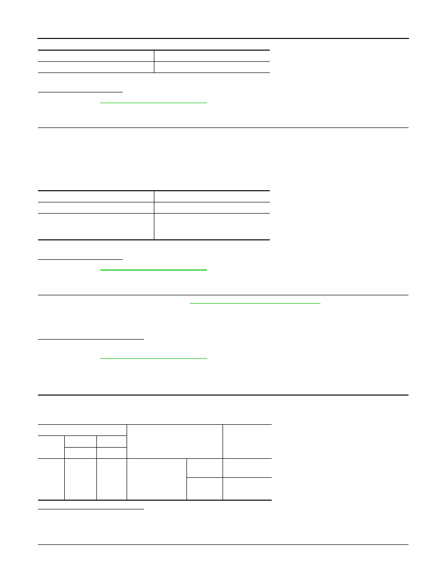
VHCL SPEED SE
More than 30 km/h (19 mph)
Selector lever
Suitable position
VHCL SPEED SE
More than 30 km/h (19 mph)
Selector lever
Suitable position
Driving location
Depress the brake pedal for more than
five seconds so as not to come off from
the above-mentioned vehicle speed.
ECM
Condition
Voltage
Con-
nector
+
–
Terminal
Terminal
E16
126
(ASCD
brake
switch
signal)
128
Brake pedal
Slightly
depressed
Approx. 0 V
Fully re-
leased
Battery voltage