Nissan Quest E52. Manual - part 537


  Index      Nissan     Nissan Quest E52 (2011-2014 year) - Service and Repair Manual


Search            


Content   ..  535  536  537  538   ..


Nissan Quest E52. Manual - part 537


EC-358

< DTC/CIRCUIT DIAGNOSIS >

[VQ35DE]

P1554 BATTERY CURRENT SENSOR
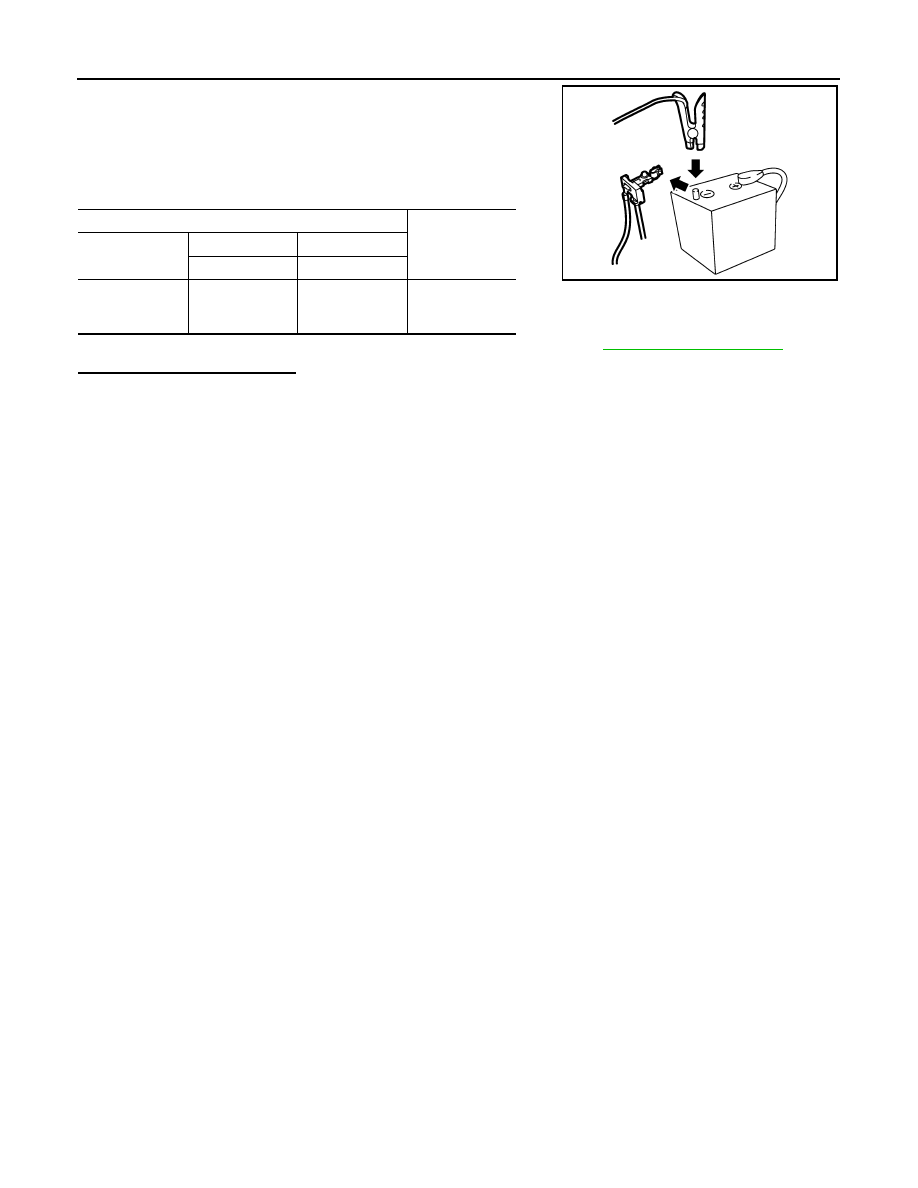
3.

Disconnect battery negative cable.

4.

Install jumper cable between battery negative terminal and body
ground.

5.

Turn ignition switch ON.

6.

Check the voltage between ECM harness connector terminals
under the following conditions.

Before measuring the terminal voltage, confirm that the battery is fully charged. Refer to 

PG-97, "How to Handle Battery"

.

Is the inspection result normal?

YES

>> INSPECTION END

NO

>> Replace battery negative cable assembly.

ECM

Voltage (V)

Connector

+

Terminal

Terminal

F8

66

(Battery current 

sensor signal)

68

(Sensor ground)

Approx. 2.5

JPBIA3287ZZ

P1556, P1557 BATTERY TEMPERATURE SENSOR

EC-359

< DTC/CIRCUIT DIAGNOSIS >

[VQ35DE]

C

D

E

F

G

H

I

J

K

L

M

A

EC

N

P

O

P1556, P1557 BATTERY TEMPERATURE SENSOR

DTC Logic

INFOID:0000000009651207

DTC DETECTION LOGIC

DTC CONFIRMATION PROCEDURE

1.

PRECONDITIONING

1.

Turn ignition switch OFF and wait at least 10 seconds.

2.

Turn ignition switch ON.

3.

Turn ignition switch OFF and wait at least 10 seconds.

TESTING CONDITION:
Before performing the following procedure, confirm that battery voltage is 10 V or more at idle.

>> GO TO 2.

2.

PERFORM DTC CONFIRMATION PROCEDURE

1.

Start the engine and let it idle at least 10 seconds.

2.

Check 1st trip DTC.

Is 1st trip DTC detected?

YES

>> Proceed to 

EC-359, "Diagnosis Procedure"

.

NO

>> INSPECTION END

Diagnosis Procedure

INFOID:0000000009651208

1.

CHECK BATTERY TEMPERATURE SENSOR INPUT SIGNAL CIRCUIT-I

1.

Disconnect battery current sensor harness connector.

2.

Turn ignition switch ON.

3.

Check the voltage between battery current sensor harness connector and ground.

Is the inspection result normal?

YES

>> GO TO 6.

NO

>> GO TO 2.

2.

CHECK BATTERY TEMPERATURE SENSOR INPUT SIGNAL CIRCUIT-II

1.

Turn ignition switch ON.

2.

Disconnect ECM harness connector.

DTC No.

Trouble diagnosis name

(Trouble diagnosis content)

DTC detecting condition

Possible cause

P1556

BAT TMP SEN/CIRC
(Battery temperature sensor cir-
cuit low input)

Signal voltage from Battery temperature 
sensor remains 0.16V or less for 5 sec-
onds or more.

• Harness or connectors

[Battery current sensor (Battery tem-
perature sensor) circuit is shorted.]
[Camshaft position sensor (PHESE) 
circuit is open or shorted.]
(Accelerator pedal position sensor 2 
circuit is shorted.)
(Throttle position sensor circuit is 
shorted.)

• Battery current sensor (Battery tem-

perature sensor)

• Camshaft position sensor (PHESE) 
• Accelerator pedal position sensor
• Throttle position sensor

P1557

BAT TMP SEN/CIRC
(Battery temperature sensor cir-
cuit high input)

Signal voltage from Battery temperature 
sensor remains 4.84V or more for 5 sec-
onds or more.

Battery current sensor

Ground

Voltage (V)

Connector

Terminal

F76

2

Ground

Approx. 5

EC-360

< DTC/CIRCUIT DIAGNOSIS >

[VQ35DE]

P1556, P1557 BATTERY TEMPERATURE SENSOR

3.

Check the continuity between battery current sensor harness connector and ECM harness connector.

Is the inspection result normal?

YES

>> GO TO 3.

NO

>> Repair open circuit.

3.

CHECK SENSOR POWER SUPPLY CIRCUIT

Check harness for short to power and short to ground, between the following terminals.

Is the inspection result normal?

YES

>> GO TO 4.

NO

>> Repair short to ground or short to power in harness or connectors.

4.

CHECK COMPONENTS

Check the following.
• Camshaft position sensor (PHESE) (Refer to 

EC-276, "Component Inspection"

.)

• Battery current sensor (Refer to 

EC-351, "Component Inspection"

.)

• Throttle position sensor (Refer to 

EC-198, "Component Inspection"

.)

Is the inspection result normal?

YES

>> GO TO 5.

NO

>> Replace malfunctioning component.

5.

CHECK APP SENSOR

Check APP sensor. Refer to 

EC-405, "Component Inspection"

.

Is the inspection result normal?

YES

>> GO TO 8.

NO

>> Replace accelerator pedal assembly. Refer to 

ACC-3, "Exploded View"

.

6.

CHECK BATTERY TEMPERATURE SENSOR GROUND CIRCUIT FOR OPEN AND SHORT

1.

Turn ignition switch OFF.

2.

Disconnect ECM harness connector.

3.

Check the continuity between battery current sensor harness connector and ECM harness connector.

4.

Also check harness for short to ground and short to power.

Is the inspection result normal?

YES

>> GO TO 7.

NO

>> Repair open circuit, short to ground or short to power in harness or connectors.

7.

CHECK BATTERY TEMPERATURE SENSOR

Check battery temperature sensor. Refer to 

EC-361, "Component Inspection (Battery Temperature Sensor)"

.

Battery current sensor

ECM

Continuity

Connector

Terminal

Connector

Terminal

F76

2

F8

67

Existed

ECM

Sensor

Connector

Terminal

Name

Connector

Terminal

F8

75

Battery current sensor

F76

1

83

CMP sensor (PHESE) bank 1

F26

87

CMP sensor (PHESE) bank 2

F69

F7

24

TP sensor

F29

1

E16

99

APP sensor

E110

4

Battery current sensor

ECM

Continuity

Connector

Terminal

Connector

Terminal

F76

3

F8

68

Existed

P1556, P1557 BATTERY TEMPERATURE SENSOR

EC-361

< DTC/CIRCUIT DIAGNOSIS >

[VQ35DE]

C

D

E

F

G

H

I

J

K

L

M

A

EC

N

P

O

Is the inspection result normal?

YES

>> GO TO 8.

NO

>> Replace battery negative cable assembly.

8.

CHECK INTERMITTENT INCIDENT

Check intermittent incident. Refer to 

GI-42, "Intermittent Incident"

.

>> INSPECTION END

Component Inspection (Battery Temperature Sensor)

INFOID:0000000009651209

1.

CHECK BATTERY TEMPERATURE SENSOR

1.

Turn ignition switch OFF.

2.

Disconnect battery current sensor.

3.

Check the resistance between battery current sensor connector terminals.

Is the inspection result normal?

YES

>> INSPECTION END

NO

>> Replace battery negative cable assembly.

Battery current sensor

Resistance

+

Terminal

2

3

continuity with the resis-
tance value 100 

 or more


Content   ..  535  536  537  538   ..