Nissan Quest E52. Manual - part 511


  Index      Nissan     Nissan Quest E52 (2011-2014 year) - Service and Repair Manual


Search            


Content   ..  509  510  511  512   ..


Nissan Quest E52. Manual - part 511


EC-254

< DTC/CIRCUIT DIAGNOSIS >

[VQ35DE]

P0182, P0183 FTT SENSOR

>> Repair open circuit, short to ground or short to power in harness or connector.

4.

CHECK FUEL TANK TEMPERATURE SENSOR GROUND CIRCUIT FOR OPEN AND SHORT

1.

Turn ignition switch OFF.

2.

Disconnect ECM harness connector.

3.

Check the continuity between “fuel level sensor unit and fuel pump” harness connector and ECM harness
connector.

4.

Also check harness for short to ground and short to power.

Is the inspection result normal?

YES

>> GO TO 6.

NO

>> GO TO 5.

5.

DETECT MALFUNCTIONING PART

Check the following.
• Harness connectors E105, M11
• Harness connectors M77, B11
• Harness for open or short between “fuel level sensor unit and fuel pump” and ECM

>> Repair open circuit, short to ground or short to power in harness or connector.

6.

CHECK FUEL TANK TEMPERATURE SENSOR

Refer to 

EC-254, "Component Inspection"

.

Is the inspection result normal?

YES

>> GO TO 7.

NO

>> Replace “fuel level sensor unit and fuel pump”.

7.

CHECK INTERMITTENT INCIDENT

Refer to 

GI-42, "Intermittent Incident"

.

>> INSPECTION END

Component Inspection

INFOID:0000000009651097
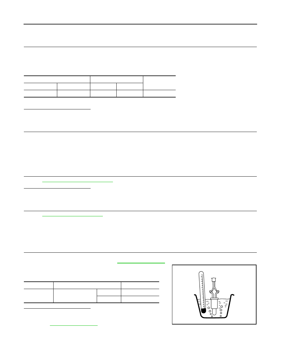
1.

CHECK FUEL TANK TEMPERATURE SENSOR

1.

Turn ignition switch OFF.

2.

Remove fuel level sensor unit. Refer to 

FL-5, "Exploded View"

.

3.

Check resistance between “fuel level sensor unit and fuel pump”
terminals by heating with hot water as shown in the figure.

Is the inspection result normal?

YES

>> INSPECTION END

NO

>> Replace fuel level sensor unit and fuel pump. Refer to

FL-5, "Exploded View"

.

Fuel level sensor unit and fuel pump

ECM

Continuity

Connector

Terminal

Connector

Terminal

B40

5

E16

120

Existed

Terminals

Condition

Resistance

4 and 5

Temperature [

°

C (

°

F)]

20 (68)

2.3 - 2.7 k

50 (122)

0.79 - 0.90 k

JMBIA0167ZZ

P0196 EOT SENSOR

EC-255

< DTC/CIRCUIT DIAGNOSIS >

[VQ35DE]

C

D

E

F

G

H

I

J

K

L

M

A

EC

N

P

O

P0196 EOT SENSOR

DTC Logic

INFOID:0000000009651098

DTC DETECTION LOGIC

NOTE:
If DTC P0196 is displayed with DTC P0197 or P0198, first perform the trouble diagnosis for DTC P0197 or
P0198. Refer to 

EC-259, "DTC Logic"

.

DTC CONFIRMATION PROCEDURE

1.

INSPECTION START

Is it necessary to erase permanent DTC?

YES

>> GO TO 6.

NO

>> GO TO 2.

2.

PRECONDITIONING

If DTC CONFIRMATION PROCEDURE has been previously conducted, always perform the following proce-
dure before conducting the next test.
1.

Turn ignition switch OFF and wait at least 10 seconds.

2.

Turn ignition switch ON.

3.

Turn ignition switch OFF and wait at least 10 seconds.

TESTING CONDITION:
Before performing the following procedure, confirm that battery voltage is 11 V or more at idle.

>> GO TO 3.

3.

PERFORM DTC CONFIRMATION PROCEDURE FOR MULFUNCTION A-I

1.

Start engine and warm it up to normal operating temperature.

2.

Turn ignition switch OFF and wait at least 10 seconds.

3.

Turn ignition switch ON.

4.

Turn ignition switch OFF and wait at least 10 seconds.

5.

Start engine and let it idle for 5 minutes and 10 seconds.

6.

Check 1st trip DTC.

Is 1st trip DTC detected?

YES

>> Proceed to 

EC-257, "Diagnosis Procedure"

.

NO

>> GO TO 4.

4.

PERFORM DTC CONFIRMATION PROCEDURE FOR MULFUNCTION A-II

With CONSULT

1.

Select “DATA MONITOR” mode with CONSULT.

2.

Check that “COOLAN TEMP/S” indicates above 70

°

C (158

°

F).

If it is above 70

°

C (158

°

F), go to the following steps.

DTC No.

Trouble diagnosis

(Trouble diagnosis content)

DTC detecting condition

Possible cause

P0196

EOT SENSOR
[Engine oil temperature (EOT) 
sensor circuit range/perfor-
mance]

A)

Rationally incorrect voltage from the 
sensor is sent to ECM, compared with 
the voltage signals from EOT sensor 
and intake air temperature sensor.

• Harness or connectors

(The EOT sensor circuit is open or 
shorted)

• EOT sensor

B)

The comparison result of signals trans-
mitted to ECM from each temperature 
sensor (IAT sensor, ECT sensor, FTT 
sensor, and EOT sensor) shows that the 
signal voltage of the EOT sensor is high-
er/lower than that of other temperature 
sensors when the engine is started with 
its cold state.

• Harness or connectors

(High or low resistance in the EOT 
sensor circuit)

• EOT sensor

EC-256

< DTC/CIRCUIT DIAGNOSIS >

[VQ35DE]

P0196 EOT SENSOR

If it is below 70

°

C (158

°

F), warm engine up until “COOLAN TEMP/S” indicates more than 70

°

C (158

°

F).

Then perform the following steps.

3.

Turn ignition switch OFF and soak the vehicle in a cool place.

4.

Turn ignition switch ON.
NOTE:
Do not turn ignition switch OFF until step 8.

5.

Select “DATA MONITOR” mode with CONSULT.

6.

Check the following.

If they are within the specified range, perform the following steps.
If they are out of the specified range, soak the vehicle to meet the above conditions. Then perform the fol-
lowing steps.
NOTE:
• Do not turn ignition switch OFF.
• If it is supposed to need a long period of time, do not deplete the battery.

7.

Start engine and let it idle for 5 minutes.

8.

Check 1st trip DTC.

With GST

Follow the procedure “With CONSULT” above.

Is 1st trip DTC detected?

YES

>> Proceed to 

EC-257, "Diagnosis Procedure"

.

NO

>> GO TO 5.

5.

PERFORM COMPONENT FUNCTION CHECK (FOR MULFUNCTION B)

Perform component function check. Refer to 

EC-257, "Component Function Check"

.

NOTE:
Use the component function check to check the overall function of the EOT sensor circuit. During this check, a
1st trip DTC might not be confirmed.

Is the inspection result normal?

YES

>> INSPECTION END

NO

>> Proceed to 

EC-257, "Diagnosis Procedure"

.

6.

PRECONDITIONING

If DTC CONFIRMATION PROCEDURE has been previously conducted, always perform the following proce-
dure before conducting the next test.
1.

Turn ignition switch OFF and wait at least 10 seconds.

2.

Turn ignition switch ON.

3.

Turn ignition switch OFF and wait at least 10 seconds.

TESTING CONDITION:
• Before performing the following procedure, do not add fuel.
• Before performing the following procedure, check that fuel level is between 1/4 and 4/4.
• Before performing the following procedure, confirm that battery voltage is 11 V or more at idle.

>> GO TO 7.

7.

PERFORM DTC CONFIRMATION PROCEDURE B

1.

Start engine and let it idle for 60 minutes.

2.

Move the vehicle to a cool place.
NOTE:
Cool the vehicle in an environment of ambient air temperature between 

10

°

C (14

°

F) and 35

°

C (95

°

F).

3.

Turn ignition switch OFF and soak the vehicle for 12 hours.

CAUTION:

Never turn ignition switch ON during soaking.
NOTE:
The vehicle must be cooled with the food open.

COOLAN TEMP/S

Below 40

°

C (104

°

F)

INT/A TEMP SE

Below 40

°

C (104

°

F)

Difference between “COOLAN TEMP/S” and “INT/A TEMP SE”

Within 6

°

C (11

°

F)

P0196 EOT SENSOR

EC-257

< DTC/CIRCUIT DIAGNOSIS >

[VQ35DE]

C

D

E

F

G

H

I

J

K

L

M

A

EC

N

P

O

4.

Start engine and let it idle for 5 minutes or more.

CAUTION:

Never turn ignition switch OFF during idling.

5.

Check 1st trip DTC.

Is 1st trip DTC detected?

YES

>> Proceed to 

EC-257, "Diagnosis Procedure"

.

NO

>> INSPECTION END

Component Function Check

INFOID:0000000009651099

1.

CHECK ENGINE OIL TEMPERATURE (EOT) SENSOR

1.

Turn ignition switch OFF.

2.

Disconnect EOT sensor harness connector.

3.

Remove EOT sensor. Refer to 

CO-26, "Exploded View"

.

4.

Check resistance between EOT sensor terminals by heating
with hot water as shown in the figure.

Is the inspection result normal?

YES

>> GO TO 2.

NO

>> Proceed to 

EC-257, "Diagnosis Procedure"

.

2.

CHECK INTERMITTENT INCIDENT

Check intermittent incident. Refer to 

GI-42, "Intermittent Incident"

.

Is the inspection result normal?

YES

>> INSPECTION END

NO

>> Proceed to 

EC-257, "Diagnosis Procedure"

.

Diagnosis Procedure

INFOID:0000000009651100

1.

CHECK ENGINE OIL TEMPERATURE SENSOR

Check engine oil temperature sensor. Refer to 

EC-257, "Component Inspection"

.

Is the inspection result normal?

YES

>> Check intermittent incident. Refer to 

GI-42, "Intermittent Incident"

.

NO

>> Replace engine oil temperature sensor. Refer to 

EM-66, "Exploded View"

.

Component Inspection

INFOID:0000000009651101

1.

CHECK ENGINE OIL TEMPERATURE SENSOR

1.

Turn ignition switch OFF.

2.

Disconnect engine oil temperature sensor harness connector.

3.

Remove engine oil temperature sensor. Refer to 

EM-66, "Exploded View"

.

4.

Check resistance between engine oil temperature sensor termi-
nals by heating with hot water as shown in the figure.

Is the inspection result normal?

YES

>> INSPECTION END

Terminals

Condition

Resistance (k

)

1 and 2

Temperature [

°

C (

°

F)]

20 (68)

2.1 – 2.9

50 (122)

0.68 – 1.00

90 (194)

0.236 – 0.260

JMBIA0080ZZ

Terminals

Condition

Resistance

1 and 2

Temperature [

°

C (

°

F)]

20 (68)

2.1 - 2.9 k

50 (122)

0.68 - 1.00 k

90 (194)

0.236 - 0.260 k

JMBIA0080ZZ


Content   ..  509  510  511  512   ..