Nissan Quest E52. Manual - part 428
DLK-426
< REMOVAL AND INSTALLATION >
HOOD
FITTING ADJUSTMENT PROCEDURE
1.
Remove front grille. Refer to
EXT-18, "Removal and Installation"
2.
Remove hood lock assembly.
3.
Temporarily install front grille, and then adjust the surface height of hood assembly, front fender assembly,
and front combination lamp according to the specified value, by rotating hood bumper rubber.
4.
Remove front grille.
5.
Position hood lock assembly and engage hood striker. Check hood lock assembly and hood striker for
looseness.
6.
Move hood lock assembly laterally until the center of hood striker and hood lock assembly are vertical
when viewed from the front.
7.
After adjustment, tighten lock bolts to the specified torque.
8.
Check that secondary latch is securely engaged with secondary striker from the dead load of the hood
assembly.
9.
Check that primary latch is securely engaged with primary striker when hood assembly is closed [free-fall
from approximately 200 mm (7.874 in) height].
CAUTION:
Never free-fall hood assembly from a height of 300 (11.811 in) mm or more.
10. Install front grille. Refer to
EXT-18, "Removal and Installation"
HOOD HINGE
HOOD HINGE : Removal and Installation
INFOID:0000000009649423
REMOVAL
1.
Remove hood assembly. Refer to
DLK-424, "HOOD ASSEMBLY : Removal and Installation"
2.
Remove front fender. Refer to
DLK-430, "FRONT FENDER : Removal and Installation"
3.
Remove hood hinge mounting bolts, and then remove hood hinge.
INSTALLATION
Note the following items, and then install in the reverse order of removal.
CAUTION:
• After installation, perform hood fitting adjustment. Refer to
DLK-425, "HOOD ASSEMBLY : Adjust-
• After installation, apply touch-up paint (the body color) onto the head of the hinge mounting bolts
and nuts.
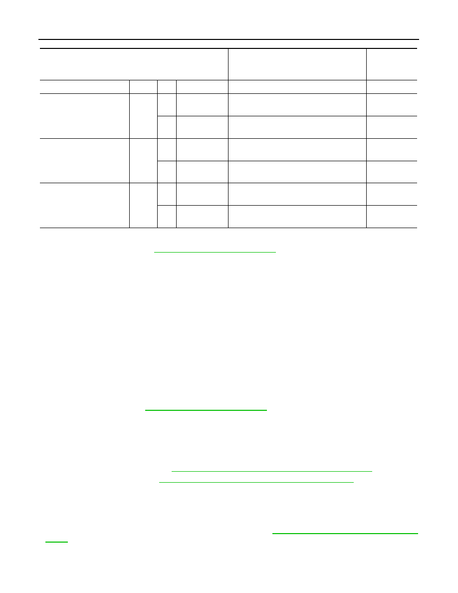
Portion
Standard
Difference
(RH/LH,
MAX)
Hood – Front grille
A – A
E
Clearance
4.0 – 8.5 mm (0.157 – 0.335 in)
—
Hood – Front combi-
nation lamp
B – B
F
Clearance
3.7 – 8.3 mm (0.146 – 0.327 in)
3.0 mm
(0.118 in)
G
Surface
height
(
−
1.7) –(+3.7) mm [(
−
0.067) –
(+0.146) in]
3.0 mm
(0.118 in)
Hood – Front fender
C – C
H
Surface
height
(
−
1.0) – (+1.0) mm [(
−
0.039) –
(+0.039) in]
1.5 mm
(0.059 in)
I
Clearance
2.7 – 4.7 mm (0.106 – 0.185 in)
1.5 mm
(0.059 in)
Hood – Front fender
D – D
J
Clearance
3.1 – 5.1 mm (0.122 – 0.201 in)
1.5 mm
(0.059 in)
K
Surface
height
(
−
1.0) – (+1.0) mm [(
−
0.039) –
(+0.039) in]
—