Nissan Quest E52. Manual - part 412
DLK-362
< DTC/CIRCUIT DIAGNOSIS >
SLIDING DOOR LOCK RELEASE ACTUATOR
2.
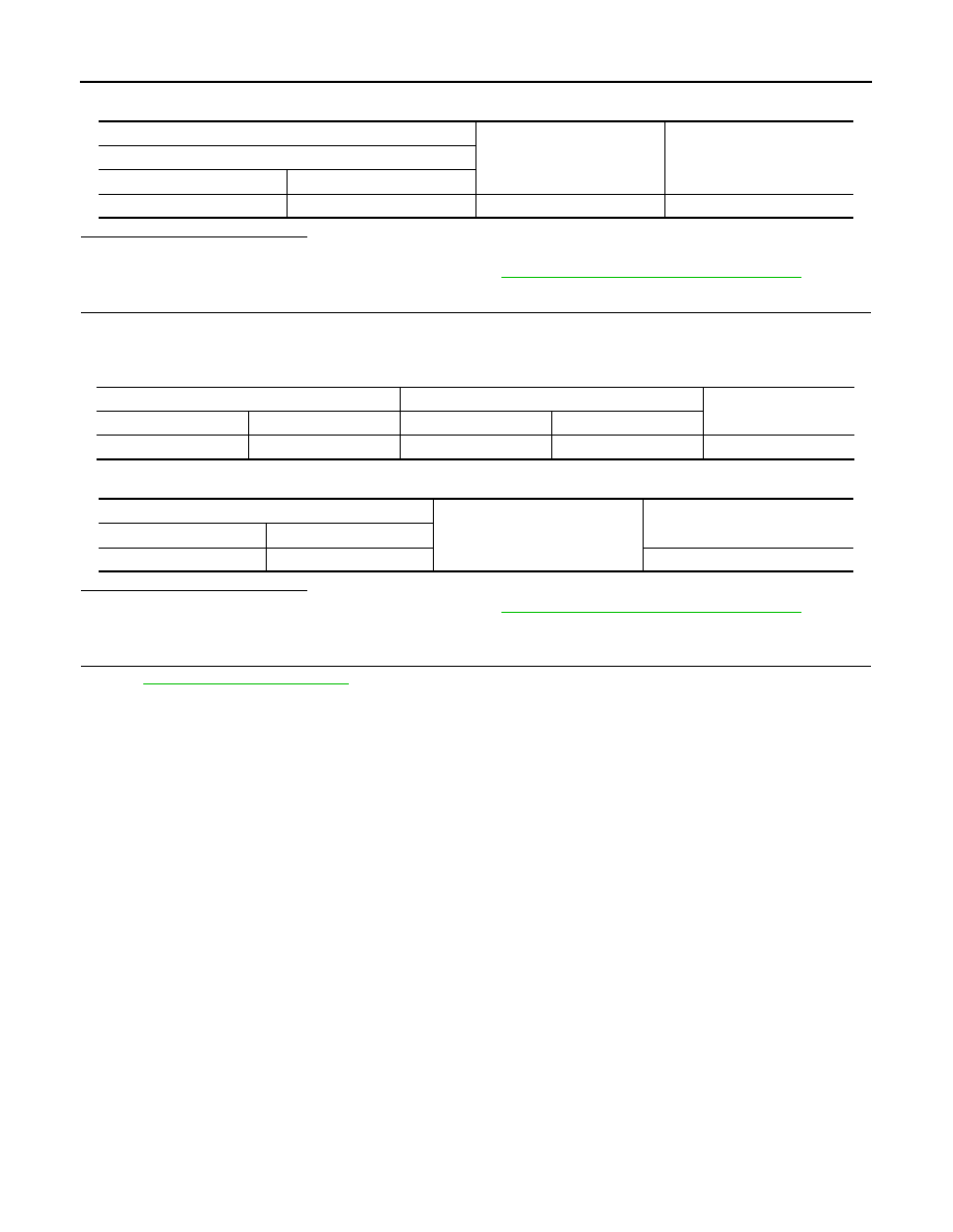
Check voltage between sliding door control unit RH harness connector and ground.
Is the inspection result normal?
YES
>> GO TO 5.
NO
>> Replace sliding door control unit RH. Refer to
DLK-500, "RH : Removal and Installation"
4.
CHECK SLIDING DOOR LOCK RELEASE ACTUATOR GROUND CIRCUIT
1.
Disconnect sliding door control unit RH connector.
2.
Check continuity between sliding door control unit RH harness connector and sliding door lock release
actuator RH harness connector.
3.
Check continuity between sliding door control unit RH harness connector and ground.
Is the inspection result normal?
YES
>> Replace sliding door control unit RH. Refer to
DLK-500, "RH : Removal and Installation"
NO
>> Repair or replace harness.
5.
CHECK INTERMITTENT INCIDENT
GI-42, "Intermittent Incident"
>> INSPECTION END
(+)
(–)
Voltage
Sliding door control unit RH
Connector
Terminal
B248
39
Ground
0 V
Sliding door control unit RH
Sliding door lock release actuator RH
Continuity
Connector
Terminal
Connector
Terminal
B248
40
D122
1
Existed
Sliding door control unit RH
Ground
Continuity
Connector
Terminal
B248
40
Not existed