Nissan Quest E52. Manual - part 397
DLK-302
< DTC/CIRCUIT DIAGNOSIS >
BACK DOOR TOUCH SENSOR
3.
CHECK BACK DOOR TOUCH SENSOR RH GROUND CIRCUIT
1.
Disconnect automatic back door control module connector and back door touch sensor RH connector.
2.
Check continuity between automatic back door control module harness connector and back door touch
sensor RH harness connector.
3.
Check continuity between automatic back door control module harness connector and ground.
Is the inspection result normal?
YES
>> GO TO 4.
NO
>> Repair or replace harness.
4.
CHECK BACK DOOR TOUCH SENSOR RH GROUND CIRCUIT 2
1.
Connect automatic back door control module connector and back door touch sensor RH connector.
2.
Check voltage between automatic back door control module harness connector and ground.
Is the inspection result normal?
YES
>> GO TO 5.
NO
>> Replace automatic back door control module. Refer to
DLK-495, "Removal and Installation"
.
5.
CHECK BACK DOOR TOUCH SENSOR RH
DLK-302, "RH : Component Inspection"
.
Is the inspection result normal?
YES
>> GO TO 6.
NO
>> Replace back door touch sensor RH.
6.
CHECK INTERMITTENT INCIDENT
GI-42, "Intermittent Incident"
>> INSPECTION END
RH : Component Inspection
INFOID:0000000009649231
1.
CHECK TOUCH SENSOR RH
1.
Turn ignition switch OFF.
2.
Disconnect back door touch sensor RH connector.
3.
Check resistance between back door touch sensor RH terminals.
Is the inspection result normal?
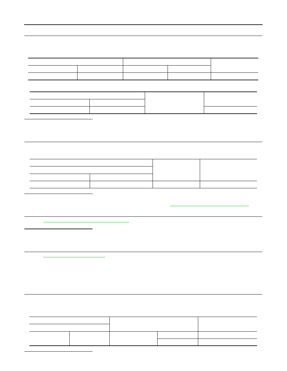
Automatic back door control module
Back door touch sensor RH
Continuity
Connector
Terminal
Connector
Terminal
B8
14
D191
2
Existed
Automatic back door control module
Ground
Continuity
Connector
Terminal
B8
14
Not existed
(+)
(–)
Voltage
Automatic back door control module
Connector
Terminal
B8
14
Ground
0 – 1.5 V
Back door touch sensor RH
Condition
Resistance
Terminal
1
2
Back door touch sensor
RH
Detect obstruction
360 - 440
Ω
Other than above
0.9 - 1.1 k
Ω