Nissan Quest E52. Manual - part 396


  Index      Nissan     Nissan Quest E52 (2011-2014 year) - Service and Repair Manual


Search            


Content   ..  394  395  396  397   ..


Nissan Quest E52. Manual - part 396


DLK-298

< DTC/CIRCUIT DIAGNOSIS >

HALF LATCH SWITCH

Sliding door RH

Is the inspection result normal?

YES

>> GO TO 5.

NO

>> Replace sliding door control unit.

5.

CHECK HALF LATCH SWITCH

Refer to 

DLK-298, "SLIDING DOOR CONTROL UNIT : Component Inspection"

.

Is the inspection result normal?

YES

>> GO TO 6.

NO

>> Replace sliding door lock assembly

6.

CHECK INTERMITTENT INCIDENT

Refer to 

GI-42, "Intermittent Incident"

.

>> INSPECTION END

SLIDING DOOR CONTROL UNIT : Component Inspection

INFOID:0000000009649225

1.

CHECK HALF LATCH SWITCH

1.

Turn ignition switch OFF.

2.

Disconnect sliding door lock assembly connector.

3.

Check continuity between sliding door lock assembly terminals.

Is the inspection result normal?

YES

>> INSPECTION END

NO

>> Replace sliding door lock assembly.
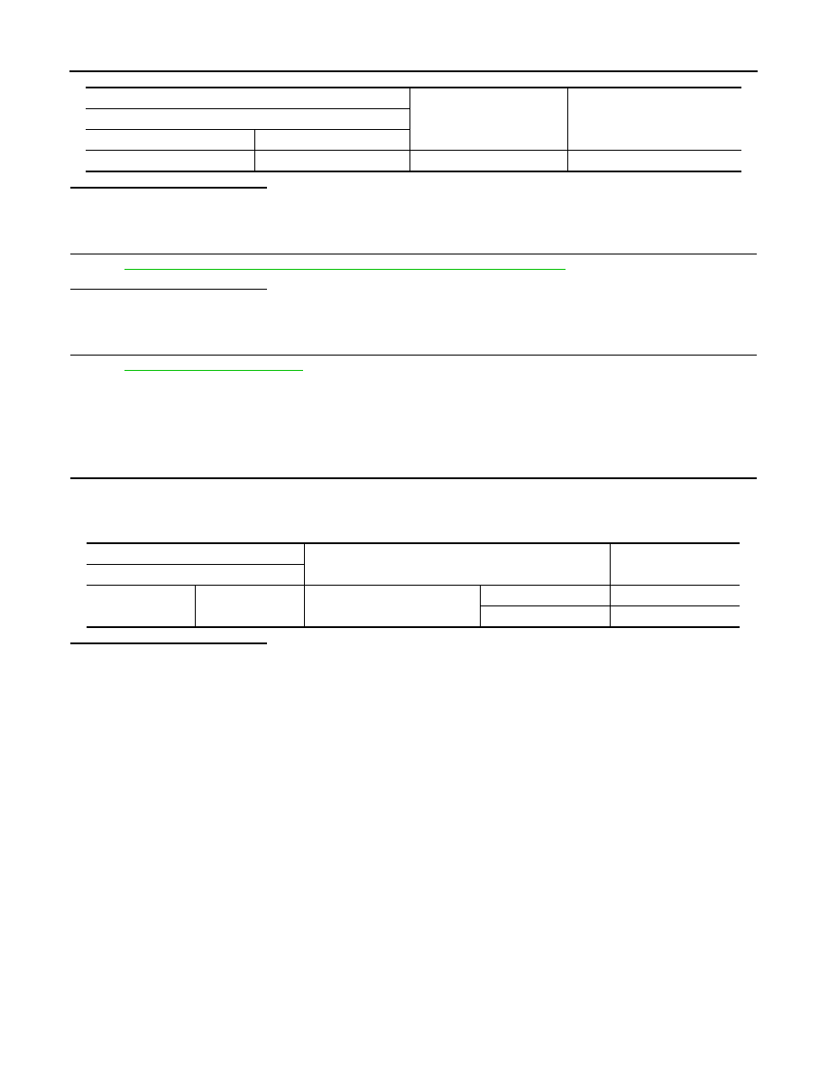
(+)

(

)

Voltage

Sliding door control unit RH

Connector

Terminal

B247

23

Ground

0 V

Sliding door lock assembly

Condition

Continuity 

Terminal

3

2

Sliding door

Open

Existed

Half latch/fully closed

Not existed

BACK DOOR TOUCH SENSOR

DLK-299

< DTC/CIRCUIT DIAGNOSIS >

C

D

E

F

G

H

I

J

L

M

A

B

DLK

N

O

P

BACK DOOR TOUCH SENSOR

LH

LH : Component Function Check

INFOID:0000000009649226

1.

CHECK FUNCTION

1.

Select “AUTO BACK DOOR” using CONSULT.

2.

Select “TOUCH SEN LH” in “DATA MONITOR” mode.

3.

Check that the function operates normally according to the following conditions.

Is the inspection result normal?

YES

>> Back door touch sensor LH is OK.

NO

>> Refer to 

DLK-299, "LH : Diagnosis Procedure"

.

LH : Diagnosis Procedure

INFOID:0000000009649227

1.

CHECK BACK DOOR TOUCH SENSOR  INPUT SIGNAL

1.

Turn ignition switch OFF.

2.

Check voltage between back door touch sensor  LH harness connector and automatic back door control
module harness connector.

Is the inspection result normal?

YES

>> GO TO 3.

NO

>> GO TO 2.

2.

CHECK BACK DOOR TOUCH SENSOR  LH CIRCUIT

1.

Disconnect automatic back door control module connector  and back door touch sensor  LH connector.

2.

Check continuity between automatic back door control module harness connector and back door touch
sensor  LH harness connector.

3.

Check continuity between automatic back door control module harness connector and ground.

Is the inspection result normal?

YES

>> Replace automatic back door control module. Refer to 

DLK-495, "Removal and Installation"

.

NO

>> Repair or replace harness.

Monitor item

Condition

Status

 TOUCH SEN LH

Back door touch sensor LH

Other than below

OFF

Detect obstruction

ON

(+)

(–)

Condition

Voltage

Back door touch sensor  LH

Automatic back door control mod-

ule

 Connector

Terminal

 Connector

Terminal

D165

1

B8

14

Back door touch 
sensor  LH

Detect obstruc-
tion

0 – 1.5 V

Other than 
above

5 – 6.7 V

Automatic back door control module

Back door touch sensor  LH

Continuity 

 Connector

Terminal

Connector

Terminal

B8

15

D165

1

Existed

Automatic back door control module

Ground

Continuity 

 Connector

Terminal

B8

15

Not existed

DLK-300

< DTC/CIRCUIT DIAGNOSIS >

BACK DOOR TOUCH SENSOR

3.

CHECK BACK DOOR TOUCH SENSOR  LH GROUND CIRCUIT

1.

Disconnect automatic back door control module connector and back door touch sensor  LH connector.

2.

Check continuity between automatic back door control module harness connector and back door touch
sensor  LH harness connector.

3.

Check continuity between automatic back door control module harness connector and ground.

Is the inspection result normal?

YES

>> GO TO 4.

NO

>> Repair or replace harness.

4.

CHECK BACK DOOR TOUCH SENSOR  LH GROUND CIRCUIT 2

1.

Connect automatic back door control module connector and back door touch sensor  LH connector.

2.

Check voltage between automatic back door control module harness connector and ground.

Is the inspection result normal?

YES

>> GO TO 5.

NO

>> Replace automatic back door control module. Refer to 

DLK-495, "Removal and Installation"

.

5.

CHECK BACK DOOR TOUCH SENSOR  LH

Refer to 

DLK-300, "LH : Component Inspection"

.

Is the inspection result normal?

YES

>> GO TO 6.

NO

>> Replace back door touch sensor  LH.

6.

CHECK INTERMITTENT INCIDENT

Refer to 

GI-42, "Intermittent Incident"

.

>> INSPECTION END

LH : Component Inspection

INFOID:0000000009649228

1.

CHECK BACK DOOR TOUCH SENSOR LH

1.

Turn ignition switch OFF.

2.

Disconnect back door touch sensor LH connector.

3.

Check resistance between back door touch sensor LH terminals.

Is the inspection result normal?

Automatic back door control module

Back door touch sensor  LH

Continuity 

 Connector

Terminal

Connector

Terminal

B8

14

D165

2

Existed

Automatic back door control module

Ground

Continuity 

 Connector

Terminal

B8

14

Not existed

(+)

(–)

Voltage

Automatic back door control module

 Connector

Terminal

B8

14

Ground

0 – 1.5 V

Back door touch sensor LH

 Condition

Resistance 

Terminal

1

2

Back door touch sensor 
LH

Detect obstruction

360 - 440 

Other than above

0.9 - 1.1 k

BACK DOOR TOUCH SENSOR

DLK-301

< DTC/CIRCUIT DIAGNOSIS >

C

D

E

F

G

H

I

J

L

M

A

B

DLK

N

O

P

YES

>> INSPECTION END

NO

>> Replace back door touch sensor LH.

RH

RH : Component Function Check

INFOID:0000000009649229

1.

CHECK FUNCTION

1.

Select “AUTO BACK DOOR” using CONSULT.

2.

Select “TOUCH SEN RH” in “DATA MONITOR” mode.

3.

Check that the function operates normally according to the following conditions.

Is the inspection result normal?

YES

>> Back door touch sensor RH is OK.

NO

>> Refer to 

DLK-301, "RH : Diagnosis Procedure"

.

RH : Diagnosis Procedure

INFOID:0000000009649230

1.

CHECK TOUCH SENSOR INPUT SIGNAL

1.

Turn ignition switch OFF.

2.

Check voltage between back door touch sensor RH harness connector and automatic back door control
module harness connector.

Is the inspection result normal?

YES

>> GO TO 3.

NO

>> GO TO 2.

2.

CHECK BACK DOOR TOUCH SENSOR RH CIRCUIT

1.

Disconnect automatic back door control module connector and back door touch sensor RH connector.

2.

Check continuity between automatic back door control module harness connector and back door touch
sensor RH harness connector.

3.

Check continuity between automatic back door control module harness connector and ground.

Is the inspection result normal?

YES

>> Replace automatic back door control module. Refer to 

DLK-495, "Removal and Installation"

.

NO

>> Repair or replace harness.

Monitor item

Condition

Status

 TOUCH SEN RH

Back door touch sensor RH

Other than below

OFF

Detect obstruction

ON

(+)

(–)

Condition

Voltage

Back door touch sensor RH

Automatic back door control mod-

ule

 Connector

Terminal

 Connector

Terminal

D191

1

B8

14

Back door touch 
sensor RH

Detect obstruc-
tion

0 – 1.5 V

Other than 
above

5 – 6.7 V

Automatic back door control module

Back door touch sensor RH

Continuity 

 Connector

Terminal

Connector

Terminal

B8

13

D191

1

Existed

Automatic back door control module

Ground

Continuity 

 Connector

Terminal

B8

13

Not existed


Content   ..  394  395  396  397   ..