Nissan Quest E52. Manual - part 376
DLK-218
< DTC/CIRCUIT DIAGNOSIS >
B2420 CLOSE SWITCH
B2420 CLOSE SWITCH
DTC Logic
INFOID:0000000009649116
DTC DETECTION LOGIC
DTC CONFIRMATION PROCEDURE
1.
PERFORM DTC CONFIRMATION PROCEDURE
1.
Turn ignition switch ON.
2.
Operate automatic back door.
3.
Check “Self Diagnostic Result” mode of “AUTO BACK DOOR” using CONSULT.
Is DTC detected?
YES
>> Refer to
DLK-218, "Diagnosis Procedure"
.
NO
>> INSPECTION END
Diagnosis Procedure
INFOID:0000000009649117
1.
CHECK AUTOMATIC BACK DOOR CONTROL MODULE OUTPUT SIGNAL
1.
Turn ignition switch OFF.
2.
Disconnect back door lock assembly connector.
3.
Check voltage between back door lock assembly harness connector and ground.
Is the inspection result normal?
YES
>> GO TO 3.
NO
>> GO TO 2.
2.
CHECK CLOSE SWITCH CIRCUIT
1.
Disconnect automatic back door control module connector.
2.
Check continuity between automatic back door control module harness connector and back door lock
assembly harness connector.
3.
Check continuity between automatic back door control module harness connector and ground.
Is the inspection result normal?
YES
>> Replace automatic back door control module. Refer to
DLK-495, "Removal and Installation"
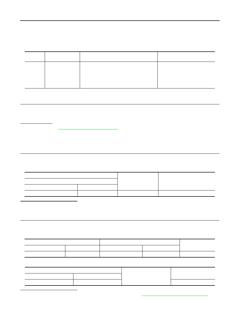
DTC
CONSULT display
description
DTC detecting condition
Possible cause
B2420
CLOSE SW
When the automatic back door control unit detects
any of the following condition
• The change of close switch cannot be detected
for 3 second or more after starting the closure
close output for the 3rd time in a row
• Close switch
• Harness or connectors
(Close switch circuit is open or
shorted)
• Automatic back door control mod-
ule
(+)
(–)
Voltage
Back door lock assembly
Connector
Terminal
D190
5
Ground
9 - 16 V
Automatic back door control module
Back door lock assembly
Continuity
Connector
Terminal
Connector
Terminal
B8
20
D190
5
Existed
Automatic back door control module
Ground
Continuity
Connector
Terminal
B8
20
Not existed