Nissan Quest E52. Manual - part 310
DAS-82
< SYMPTOM DIAGNOSIS >
[BSW]
BSW SYSTEM SYMPTOMS
SYMPTOM DIAGNOSIS
BSW SYSTEM SYMPTOMS
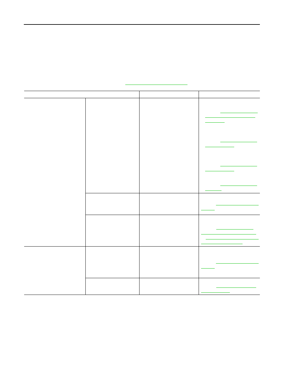
Symptom Table
INFOID:0000000009940773
CAUTION:
Perform the self-diagnosis with CONSULT before the symptom diagnosis. Perform the trouble diagno-
sis if any DTC is detected.
NOTE:
For the operational conditions of BSW, refer to
Symptom
Possible cause
Inspection item/Reference page
Indicator/warning lamps do not il-
luminate when ignition switch
OFF
⇒
ON.
BSW warning lamp (Yellow)
does not illuminate
• BSW warning lamp signal
(CAN)
- Combination meter
- BSW control module
• BSW warning lamp (combina-
tion meter)
• Power supply and ground cir-
cuit of BSW control module
Refer to
TROL MODULE : Diagnosis
Procedure"
• BSW control module Active
test “BSW/BSI WARNING
LAMP”
Refer to
.
• BSW control module Data
monitor “BSW/BSI WARN
LMP”
Refer to
• Combination meter Data mon-
itor “BSW W/L”
Refer to
BSW ON indicator (on the
BSW switch) does not illumi-
nate
• Harness between BSW con-
trol module and BSW switch
• BSW switch
• BSW control module
BSW ON indicator circuit
Refer to
BSW indicator does not turn
ON
• Harness between side radar
and BSW indicator
• Side radar LH/RH
• BSW indicator
Perform self-diagnosis of side ra-
dar
Refer to
BSW system is not activated.
(Indicator/warning lamps illumi-
nate when ignition switch OFF
⇒
ON.)
BSW ON indicator is not
turned ON
⇔
OFF when op-
erating BSW switch
• Harness between BSW con-
trol module and BSW switch
• Harness between BSW
switch and ground
• BSW control module
• BSW switch
BSW ON indicator circuit
Refer to
Buzzer is not sounding
• BSW control module
• Combination meter
Meter buzzer circuit
Refer to