Nissan Quest E52. Manual - part 246
C1130 ENGINE SIGNAL
BRC-77
< DTC/CIRCUIT DIAGNOSIS >
[WITH VDC]
C
D
E
G
H
I
J
K
L
M
A
B
BRC
N
O
P
C1130 ENGINE SIGNAL
DTC Logic
INFOID:0000000009651395
DTC DETECTION LOGIC
DTC CONFIRMATION PROCEDURE
1.
PRECONDITIONING
If “DTC CONFIRMATION PROCEDURE” has been previously conducted, always turn ignition switch OFF and
wait at least 10 seconds before conducting the next test.
>> GO TO 2.
2.
CHECK DTC DETECTION
With CONSULT
1.
Turn the ignition switch OFF to ON.
2.
Perform self-diagnosis for “ABS”.
Is DTC “C1130” detected?
YES
>> Proceed to
NO
>> INSPECTION END
Diagnosis Procedure
INFOID:0000000009651396
1.
CHECK ENGINE SYSTEM
With
CONSULT
Perform self-diagnosis for “ENGINE”.
Is any DTC detected?
YES
>> Check the DTC.
NO
>> GO TO 2.
2.
CHECK ABS ACTUATOR AND ELECTRIC UNIT (CONTROL UNIT)
With
CONSULT
1.
Erase self-diagnosis result for “ABS”.
2.
Turn the ignition switch OFF.
3.
Start the engine and drive the vehicle for a short period of time.
4.
Stop the vehicle.
5.
Check that the malfunction indicator lamp (MIL) turns OFF.
6.
After the vehicle stops, perform self-diagnosis for “ABS”.
Is DTC “C1130” detected?
YES
>> Replace ABS actuator and electric unit (control unit). Refer to
BRC-123, "Removal and Installa-
.
NO
>> Check pin terminals and connection of each harness connector for abnormal conditions. Repair or
replace error-detected parts.
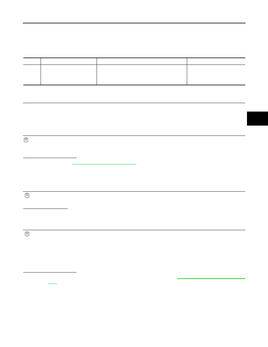
DTC
Display Item
Malfunction detected condition
Possible causes
C1130
ENGINE SIGNAL 1
When a malfunction is detected in ECM system.
• ECM
• ABS actuator and electric unit
(control unit)
• CAN communication line