Nissan Quest E52. Manual - part 245
C1120, C1122, C1124, C1126 ABS IN VALVE SYSTEM
BRC-73
< DTC/CIRCUIT DIAGNOSIS >
[WITH VDC]
C
D
E
G
H
I
J
K
L
M
A
B
BRC
N
O
P
C1120, C1122, C1124, C1126 ABS IN VALVE SYSTEM
DTC Logic
INFOID:0000000009651391
DTC DETECTION LOGIC
DTC CONFIRMATION PROCEDURE
1.
PRECONDITIONING
If “DTC CONFIRMATION PROCEDURE” has been previously conducted, always turn ignition switch OFF and
wait at least 10 seconds before conducting the next test.
>> GO TO 2.
2.
CHECK DTC DETECTION
With CONSULT
1.
Turn the ignition switch OFF to ON.
2.
Perform self-diagnosis for “ABS”.
Is DTC “C1120”, “C1122”, “C1124” or “C1126” detected?
YES
>> Proceed to
NO
>> INSPECTION END
Diagnosis Procedure
INFOID:0000000009651392
1.
CHECK CONNECTOR
1.
Turn the ignition switch OFF.
2.
Check ABS actuator and electric unit (control unit) harness connector for disconnection or looseness.
Is the inspection result normal?
YES
>> GO TO 3.
NO
>> Repair or replace error-detected parts, securely lock the connector, and GO TO 2.
2.
PERFORM SELF-DIAGNOSIS
Perform self-diagnosis for “ABS” again.
Is DTC “C1120”, “C1122”, “C1124” or “C1126” detected?
YES
>> GO TO 3.
NO
>> INSPECTION END
3.
CHECK ABS IN VALVE POWER SUPPLY
1.
Turn the ignition switch OFF.
2.
Disconnect ABS actuator and electric unit (control unit) harness connector.
3.
Check voltage between ABS actuator and electric unit (control unit) harness connector and ground.
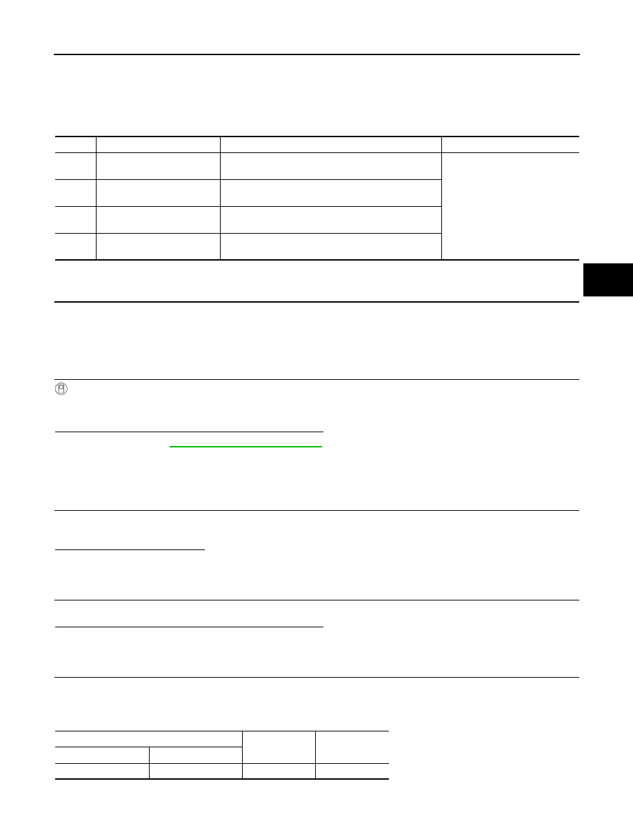
DTC
Display Item
Malfunction detected condition
Possible causes
C1120
FR LH IN ABS SOL
When a malfunction is detected in front LH ABS IN
valve.
• Harness or connector
• ABS actuator and electric unit
(control unit)
• Fusible link
• Battery power supply system
C1122
FR RH IN ABS SOL
When a malfunction is detected in front RH ABS IN
valve.
C1124
RR LH IN ABS SOL
When a malfunction is detected in rear LH ABS IN
valve.
C1126
RR RH IN ABS SOL
When a malfunction is detected in rear RH ABS IN
valve.
ABS actuator and electric unit (control unit)
—
Voltage
Connector
Terminal
E36
1
Ground
10
−
16 V