Nissan Quest E52. Manual - part 176


  Index      Nissan     Nissan Quest E52 (2011-2014 year) - Service and Repair Manual


Search            


Content   ..  174  175  176  177   ..


Nissan Quest E52. Manual - part 176


AV

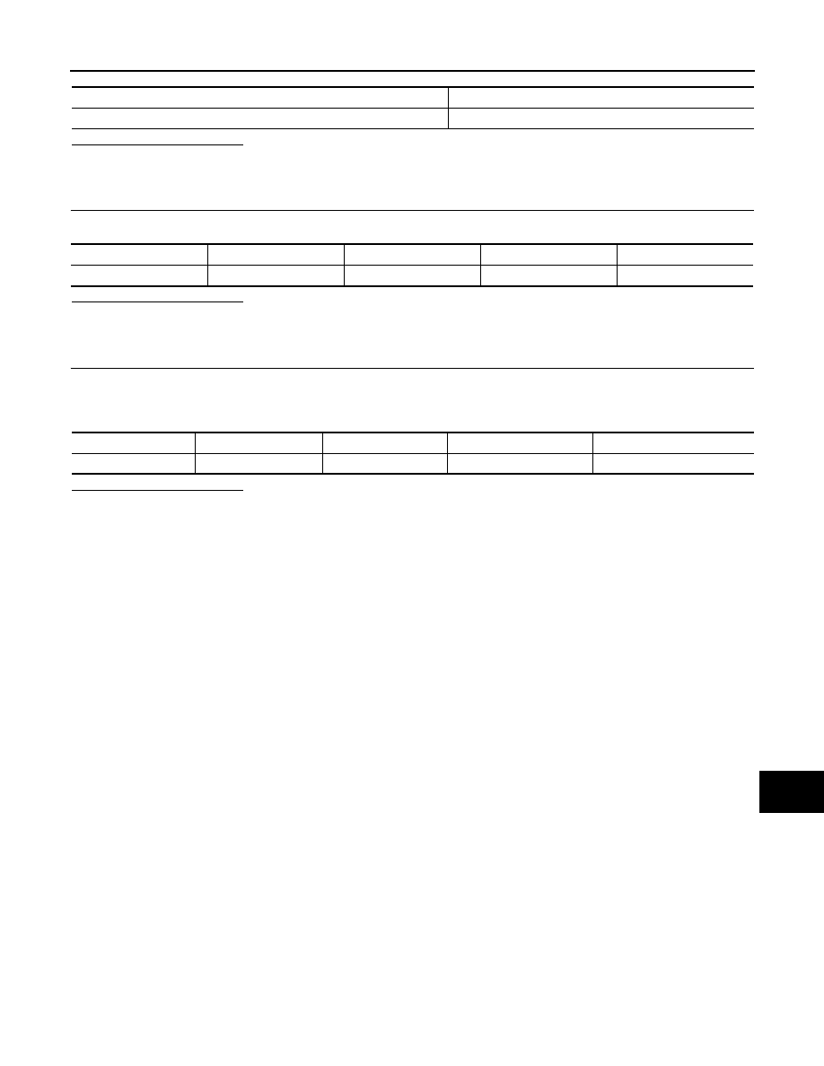
POWER SUPPLY AND GROUND CIRCUIT

AV-583

< DTC/CIRCUIT DIAGNOSIS >

[BOSE AUDIO WITH NAVIGATION]

C

D

E

F

G

H

I

J

K

L

M

B

A

O

P

Is inspection result normal?

YES

>> GO TO 2.

NO

>> Be sure to eliminate cause of malfunction before installing new fuse.

2.

CHECK POWER SUPPLY CIRCUITS

Check voltage between around view monitor control unit harness connector and ground.

Is inspection result normal?

YES

>> GO TO 3.

NO

>> Check harness between around view monitor control unit and fuse.

3.

CHECK GROUND CIRCUIT

1.

Turn ignition switch OFF.

2.

Disconnect around view monitor control unit connector.

3.

Check continuity between around view monitor control unit harness connector and ground.

Is inspection result normal?

YES

>> INSPECTION END

NO

>> Repair harness or connector.

Power source

Fuse No.

Battery

35

Signal name

Connector

Terminal

Ignition switch position

Value (Approx.)

Battery power supply

M253

2

OFF

Battery voltage

Signal name

Connector

Terminal

Ignition switch position

Continuity 

Ground

M253

1

OFF

Existed

AV-584

< DTC/CIRCUIT DIAGNOSIS >

[BOSE AUDIO WITH NAVIGATION]

COMPOSITE IMAGE SIGNAL CIRCUIT (AV CONTROL UNIT TO FRONT DIS-

PLAY UNIT)

COMPOSITE IMAGE SIGNAL CIRCUIT (AV CONTROL UNIT TO FRONT
DISPLAY UNIT)

Description

INFOID:0000000009652379

The AV control unit outputs image signal (DVD, USB memory-stored video data, and auxiliary input) to the
front display unit and rear display unit by composite image signal.

Diagnosis Procedure

INFOID:0000000009652380

1.

CHECK CONTINUITY COMPOSITE IMAGE SIGNAL CIRCUIT (AV CONTROL UNIT TO FRONT DISPLAY

UNIT)

1.

Turn ignition switch OFF.

2.

Disconnect AV control unit connector and front display unit connector.

3.

Check continuity between AV control unit harness connector and front display unit harness connector.

4.

Check continuity between AV control unit harness connector and ground.

Is the inspection result normal?

YES

>> GO TO 2.

NO

>> Repair harness or connector.

2.

CHECK COMPOSITE IMAGE SIGNAL (AV CONTROL UNIT TO FRONT DISPLAY UNIT)

1.

Connect AV control unit connector and front display unit connector.

2.

Turn ignition switch ON.

3.

Check signal between front display unit harness connector.

Is the inspection result normal?

YES

>> Replace front display unit. Refer to 

AV-611, "Removal and Installation"

.

NO

>> Replace AV control unit. Refer to 

AV-610, "Removal and Installation"

.

AV control unit

Front display unit

Continuity

Connector

Terminal

Connector

Terminal

M180

67

M155

19

Existed

68

18

AV control unit

Ground

Continuity

Connector

Terminal

M180

67

Not existed

68

Probe

Condition

Standard

Reference value

(+)

(+)

Front display unit

Connector

Terminal

Connector

Terminal

M155

18

M155

19

When DVD, 
USB or AUX 
image is dis-
played.

Waveform according to 
composite image is in-
put.

SKIB2251J

AV

COMPOSITE IMAGE SIGNAL CIRCUIT (AV CONTROL UNIT TO REAR DISPLAY 

UNIT)

AV-585

< DTC/CIRCUIT DIAGNOSIS >

[BOSE AUDIO WITH NAVIGATION]

C

D

E

F

G

H

I

J

K

L

M

B

A

O

P

COMPOSITE IMAGE SIGNAL CIRCUIT (AV CONTROL UNIT TO REAR DIS-
PLAY UNIT)

Description

INFOID:0000000009652381

The AV control unit outputs image signal (DVD, USB memory-stored video data, and auxiliary input) to the
front display unit and rear display unit by composite image signal.

Diagnosis Procedure

INFOID:0000000009652382

1.

CHECK CONTINUITY COMPOSITE IMAGE SIGNAL CIRCUIT (AV CONTROL UNIT TO REAR DISPLAY

UNIT)

1.

Turn ignition switch OFF.

2.

Disconnect AV control unit connector and rear display unit connector.

3.

Check continuity between AV control unit harness connector and rear display unit harness connector.

4.

Check continuity between AV control unit harness connector and ground.

Is the inspection result normal?

YES

>> GO TO 2.

NO

>> Repair harness or connector.

2.

CHECK COMPOSITE IMAGE SIGNAL (AV CONTROL UNIT TO REAR DISPLAY UNIT)

1.

Connect AV control unit and rear display unit connector.

2.

Turn ignition switch ON.

3.

Check signal between rear display unit harness connector.

Is the inspection result normal?

YES

>> Replace rear display unit. Refer to 

AV-612, "Removal and Installation"

.

NO

>> Replace AV control unit. Refer to 

AV-610, "Removal and Installation"

.

AV control unit

Rear display unit

Continuity

Connector

Terminal

Connector

Terminal

M179

34

R36

7

Existed

33

8

AV control unit

Ground

Continuity

Connector

Terminal

M179

34

Not existed

33

Probe

Condition

Standard

Reference value

(+)

(

)

Rear display unit

Connector

Terminal

Connector

Terminal

R36

7

R36

8

When DVD, 
USB or AUX 
image is dis-
played.

Waveform according to 
composite image is in-
put.

SKIB2251J

AV-586

< DTC/CIRCUIT DIAGNOSIS >

[BOSE AUDIO WITH NAVIGATION]

RGB DIGITAL IMAGE SIGNAL CIRCUIT

RGB DIGITAL IMAGE SIGNAL CIRCUIT

Description

INFOID:0000000009652383

Transmit the image displayed with AV control unit with RGB digital image signal to the front display unit.

Diagnosis Procedure

INFOID:0000000009652384

1.

CHECK CONTINUITY RGB DIGITAL IMAGE SIGNAL CIRCUIT

1.

Turn ignition switch OFF.

2.

Disconnect AV control unit connector and front display unit connector.

3.

Check continuity between AV control unit harness connector and front display unit harness connector.

4.

Check continuity between AV control unit harness connector and ground.

Is the inspection result normal?

YES

>> GO TO 2.

NO

>> Repair harness or connector.

2.

CHECK RGB DIGITAL IMAGE SIGNAL

1.

Connect AV control unit connector.

2.

Turn ignition switch ON.

3.

Check signal between front display unit harness connector and ground.

Is the inspection result normal?

YES

>> Replace front display unit. Refer to 

AV-611, "Removal and Installation"

.

NO

>> Replace AV control unit. Refer to 

AV-610, "Removal and Installation"

.

AV control unit

Front display unit

Continuity

Connector

Terminals

Connector

Terminals

M357

157

M358

27

Existed

158

28

AV control unit

Ground

Continuity

Connector

Terminals

M357

157

Not existed

158

Probe

Voltage

(Approx.)

(+)

(

)

AV control unit

Connector

Terminal

M357

157

Ground

3.0 V

158


Content   ..  174  175  176  177   ..