Nissan Quest E52. Manual - part 166
AV
U111C FRONT CAMERA IMAGE SIGNAL CIRCUIT
AV-543
< DTC/CIRCUIT DIAGNOSIS >
[BOSE AUDIO WITH NAVIGATION]
C
D
E
F
G
H
I
J
K
L
M
B
A
O
P
4.
Check continuity between around view monitor control unit harness connector and ground.
Is inspection result normal?
YES
>> GO TO 4.
NO
>> Repair harness or connector.
4.
CHECK FRONT CAMERA IMAGE SIGNAL
1.
Connect around view monitor control unit connector and front camera connector.
2.
Turn ignition switch ON.
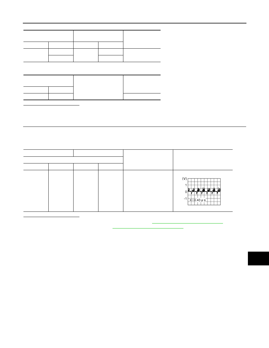
3.
Check signal between around view monitor control unit harness connector.
Is inspection result normal?
YES
>> Replace around view monitor control unit. Refer to
AV-631, "Removal and Installation"
NO
>> Replace front camera. Refer to
AV-632, "Removal and Installation"
.
Around view monitor control
unit
Front camera
Continuity
Connector
Terminals
Connector
Terminals
M253
40
E404
3
Existed
39
4
Around view monitor control
unit
Ground
Continuity
Connector
Terminals
M253
39, 40
Not existed
(+)
(
−
)
Condition
Reference value
Around view monitor control unit
Connector
Terminal
Connector
Terminal
M253
40
M253
39
“CAMERA” switch is ON or
shift position is “R”.
JSNIA0834GB