Nissan Quest E52. Manual - part 125
AV
COMPOSITE IMAGE SIGNAL CIRCUIT (AV CONTROL UNIT TO FRONT DIS-
PLAY UNIT)
AV-379
< DTC/CIRCUIT DIAGNOSIS >
[BOSE AUDIO WITHOUT NAVIGATION]
C
D
E
F
G
H
I
J
K
L
M
B
A
O
P
COMPOSITE IMAGE SIGNAL CIRCUIT (AV CONTROL UNIT TO FRONT
DISPLAY UNIT)
Description
INFOID:0000000009652190
The AV control unit outputs image signal (DVD, auxiliary input, and camera) to the front display unit and rear
display unit by composite image signal.
Diagnosis Procedure
INFOID:0000000009652191
1.
CHECK CONTINUITY COMPOSITE IMAGE SIGNAL CIRCUIT (AV CONTROL UNIT TO FRONT DISPLAY
UNIT)
1.
Turn ignition switch OFF.
2.
Disconnect AV control unit connector and front display unit connector.
3.
Check continuity between AV control unit harness connector and front display unit harness connector.
4.
Check continuity between AV control unit harness connector and ground.
Is inspection result normal?
YES
>> GO TO 2.
NO
>> Repair harness or connector.
2.
CHECK COMPOSITE IMAGE SIGNAL (AV CONTROL UNIT TO FRONT DISPLAY UNIT)
1.
Connect AV control unit connector and front display unit connector.
2.
Turn ignition switch ON.
3.
Check signal between front display unit harness connector.
Is inspection result normal?
YES
>> Replace front display unit. Refer to
AV-405, "Removal and Installation"
.
NO
>> Replace AV control unit. Refer to
AV-404, "Removal and Installation"
.
AV control unit
Front display unit
Continuity
Connector
Terminal
Connector
Terminal
M172
46
M156
4
Existed
47
15
AV control unit
Ground
Continuity
Connector
Terminal
M172
46
Not existed
47
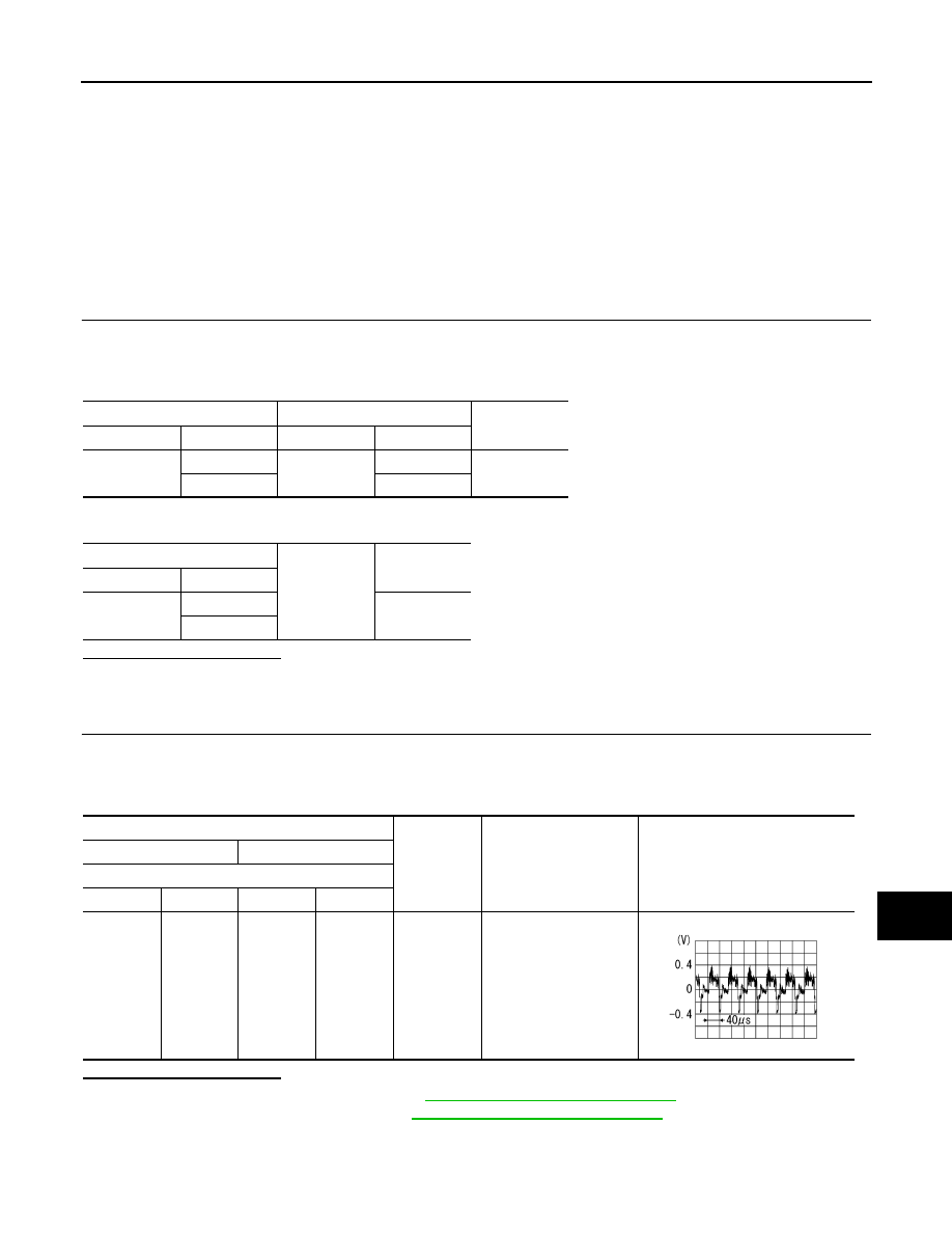
Probe
Condition
Standard
Reference value
(+)
(
−
)
Front display unit
Connector
Terminal
Connector
Terminal
M156
15
M156
4
When DVD,
AUX or cam-
era image is
displayed.
Waveform according to
composite image is in-
put.
SKIB2251J