Nissan Quest E52. Manual - part 124
AV
RGB SYNCHRONIZING SIGNAL CIRCUIT
AV-375
< DTC/CIRCUIT DIAGNOSIS >
[BOSE AUDIO WITHOUT NAVIGATION]
C
D
E
F
G
H
I
J
K
L
M
B
A
O
P
RGB SYNCHRONIZING SIGNAL CIRCUIT
Description
INFOID:0000000009652182
Transmit the RGB synchronizing signal to the front display unit so as to synchronize the RGB image displayed
with AV control unit.
Diagnosis Procedure
INFOID:0000000009652183
1.
CHECK CONTINUITY RGB SYNCHRONIZING SIGNAL CIRCUIT
1.
Turn ignition switch OFF.
2.
Disconnect front display unit connector and AV control unit connector.
3.
Check continuity between front display unit harness connector and AV control unit harness connector.
4.
Check continuity between front display unit harness connector and ground.
Is the inspection result normal?
YES
>> GO TO 2.
NO
>> Repair harness or connector.
2.
CHECK RGB SYNCHRONIZING SIGNAL
1.
Connect front display unit connector and AV control unit connector.
2.
Turn ignition switch ON.
3.
Check signal between front display unit harness connector and ground.
Is the inspection result normal?
YES
>> Replace front display unit. Refer to
AV-405, "Removal and Installation"
.
NO
>> Replace AV control unit. Refer to
AV-404, "Removal and Installation"
.
Front display unit
AV control unit
Continuity
Connector
Terminal
Connector
Terminal
M156
19
M172
42
Existed
Front display unit
Ground
Continuity
Connector
Terminal
M156
19
Not existed
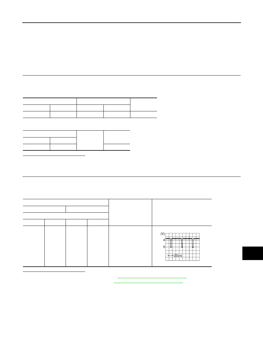
Probe
Standard
Reference value
(+)
(-)
Front display unit
Connector
Terminal
Connector
Terminal
M156
19
M156
1
Waveform of 0.8 V - 5.5
V is input.
SKIB3603E