Content .. 1247 1248 1249 1250 ..
Nissan Quest E52. Manual - part 1249
WCS-26
< ECU DIAGNOSIS INFORMATION >
COMBINATION METER
5
(B/P)
Ground
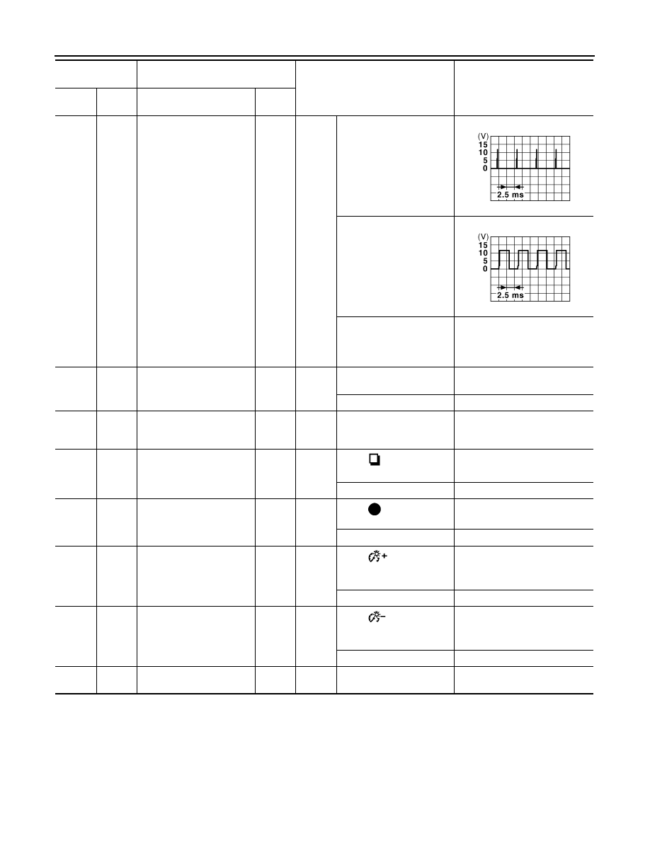
Illumination control signal
Output
Ignition
switch
ON
• Lighting switch 1ST posi-
tion
• When meter illumination
is maximum
• Lighting switch 1ST posi-
tion
• When meter illumination
is step 11
• Lighting switch 1ST posi-
tion
• When meter illumination
is minimum
12 V
8
(SB)
10
(P)
Trip reset switch signal
Input
Ignition
switch
ON
When trip reset switch is
pressed
0 V
Other than the above
5 V
10
(P)
Ground
Meter control switch ground
—
Ignition
switch
ON
—
0 V
11
(G)
10
(P)
Enter switch signal
Input
Ignition
switch
ON
When
switch (enter
switch) is pressed
0 V
Other than the above
5 V
12
(BR)
10
(P)
Select switch signal
Input
Ignition
switch
ON
When
switch
(select
switch) is pressed
0 V
Other than the above
5 V
13
(Y)
10
(P)
Illumination control switch
signal (+)
Input
Ignition
switch
ON
When
switch [illumi-
nation control switch (+)] is
pressed
0 V
Other than the above
5 V
14
(V)
10
(P)
Illumination control switch
signal (
−
)
Input
Ignition
switch
ON
When
switch
[illumi-
nation control switch (
−
)] is
pressed
0 V
Other than the above
5 V
15
(BR)
—
Air bag signal
Input
—
—
—
Terminal No.
(Wire color)
Description
Condition
Value
(Approx.)
+
–
Signal name
Input/
Output
JPNIA1687GB
JPNIA1686GB