Nissan Quest E52. Manual - part 1199


  Index      Nissan     Nissan Quest E52 (2011-2014 year) - Service and Repair Manual


Search            


Content   ..  1197  1198  1199  1200   ..


Nissan Quest E52. Manual - part 1199


TM-26

< SYSTEM DESCRIPTION >

[CVT: RE0F09B]

SYSTEM

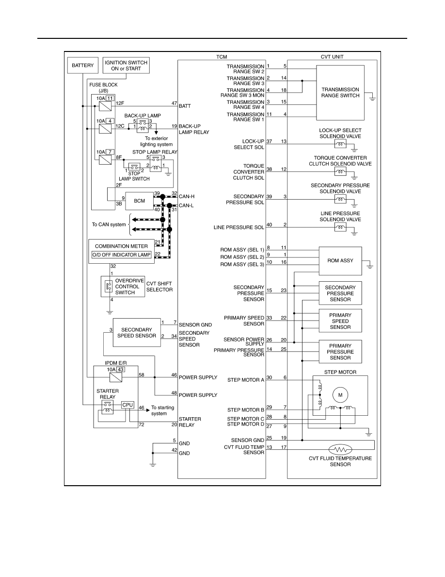
CVT CONTROL SYSTEM : Circuit Diagram

INFOID:0000000009650086

CVT CONTROL SYSTEM : Fail-safe

INFOID:0000000009650087

DESCRIPTION

TCM has a fail-safe mode. The mode functions so that operation can be continued even if the signal circuit
ofthe main electronically controlled input/output parts is damaged.

JSDIA5054GB

SYSTEM

TM-27

< SYSTEM DESCRIPTION >

[CVT: RE0F09B]

C

E

F

G

H

I

J

K

L

M

A

B

TM

N

O

P

DTC

Conditions of vehicle

Vehicle behavior

P0615

Does not start the engine

P0703

• Start  is  slow
• Acceleration is slow

P0705

• Selector shock is large
• Start  is  slow
• Acceleration is slow
• “L” position cannot be recognized
• Lock-up is not performed
• Shift position indicator on combination meter is not displayed

P0710

Engine coolant temperature when engine 
starts is 10

°

C (50

°

F) or more.

Acceleration is slow

Engine coolant temperature when engine 
starts is less than 10

°

C (50

°

F).

• Start  is  slow
• Acceleration is slow
• Vehicle speed is not increased

Engine coolant temperature when engine 
starts is less than 

35

°

C (

31

°

F).

Vehicle speed is not increased

P0715

• Acceleration is slow
• Restart is slow after stopping with strong deceleration
• “L” position cannot be recognized
• Lock-up is not performed

P0720

• Start  is  slow
• Acceleration is slow
• Restart is slow after stopping with strong deceleration
• “L” position cannot be recognized
• Lock-up is not performed

P0725

Lock-up is not performed

P0740

• Selector shock is large
• Lock-up is not performed

P0744

Lock-up is not performed

P0745

P0746

• Start  is  slow
• Acceleration is slow
• Lock-up is not performed

Function deterioration is remarkable after de-
tection of malfunction

• Start is difficulty
• Driving is difficulty
• Lock-up is not performed

P0776

P0778

Vehicle speed is not increased

P0840

• Start  is  slow
• Acceleration is slow

P0841

• Start  is  slow
• Acceleration is slow

P0845

• Start  is  slow
• Acceleration is slow

P0868

• Start  is  slow
• Acceleration is slow

P1701

• Start  is  slow
• Acceleration is slow

P1705

• Acceleration is slow
• Lock-up is not performed

P1709

• Start  is  slow
• Acceleration is slow
• Shift position indicator (P, N) is not displayed, or is displayed with delay

TM-28

< SYSTEM DESCRIPTION >

[CVT: RE0F09B]

SYSTEM

OIL PRESSURE CONTROL SYSTEM

P1722

Lock-up is not performed in coast condition

P1723

When detected malfunction of primary speed 
sensor

• Acceleration is slow
• Restart is slow after stopping with strong deceleration
• “L” position cannot be recognized
• Lock-up is not performed

When detected malfunction of secondary 
speed sensor

• Start  is  slow
• Acceleration is slow
• Restart is slow after stopping with strong deceleration
• “L” position cannot be recognized
• Lock-up is not performed

P1726

Acceleration is slow

P1740

• Selector shock is large
• Lock-up is not performed

P1777

When detected malfunction of low side (stop 
the vehicle)

• Vehicle speed is not increased
• Lock-up is not performed

When detected malfunction of high side 
(driving the vehicle)

• Start  is  slow
• Acceleration is slow
• Lock-up is not performed

U0100

• Start  is  slow
• Acceleration is slow
• Vehicle speed is not increased

U1000

• Start  is  slow
• Acceleration is slow
• Vehicle speed is not increased

U1010

• Start  is  slow
• Acceleration is slow
• Vehicle speed is not increased

DTC

Conditions of vehicle

Vehicle behavior

SYSTEM

TM-29

< SYSTEM DESCRIPTION >

[CVT: RE0F09B]

C

E

F

G

H

I

J

K

L

M

A

B

TM

N

O

P

OIL PRESSURE CONTROL SYSTEM : System Diagram

INFOID:0000000009650088

OIL PRESSURE CONTROL SYSTEM : System Description

INFOID:0000000009650089

The hydraulic control mechanism consists of the oil pump directly driven by the engine, the hydraulic control
valve that controls line pressure and transmission, and the input signal line.

LINE PRESSURE AND SECONDARY PRESSURE CONTROL

• When an input torque signal equivalent to the engine driving force is transmitted from the ECM to the TCM,

the TCM controls the line pressure solenoid valve and secondary pressure solenoid valve.

• Highly accurate line pressure control and secondary pressure control reduces friction for improvement of

fuel economy.

Normal Oil Pressure Control

JSDIA1369GB

JSDIA2455GB


Content   ..  1197  1198  1199  1200   ..