Nissan Quest E52. Manual - part 112
AV
SATELLITE RADIO TUNER
AV-327
< ECU DIAGNOSIS INFORMATION >
[BOSE AUDIO WITHOUT NAVIGATION]
C
D
E
F
G
H
I
J
K
L
M
B
A
O
P
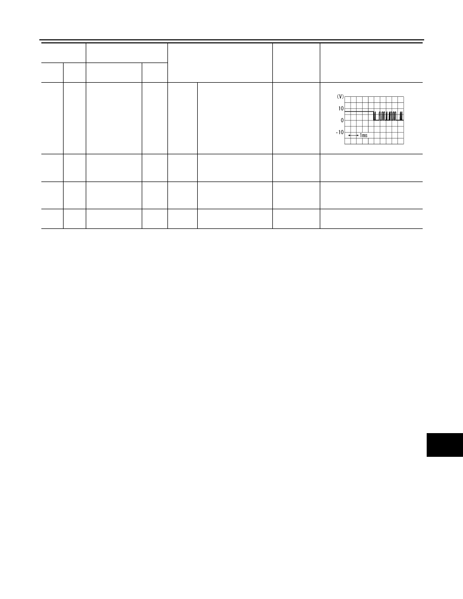
10
(R/B)
15
(B)
Communication
signal
(CONT TO SAT)
Input
Ignition
switch
ON
When satellite radio
mode is selected.
Waveform of
1.5 - 6.0 V is
input.
12
(LG)
15
(B)
Battery power
supply
Input
Ignition
switch
OFF
—
10.8 - 15.6 V
Battery voltage
16
(O)
15
(B)
ACC power sup-
ply
Input
Ignition
switch
ACC
—
7.0 - 16.0 V
Battery voltage
33
—
Satellite radio an-
tenna signal
Input
—
—
—
—
Terminal
(Wire color)
Description
Condition
Standard
Reference value
(Approx.)
+
–
Signal name
Input/
Output
SKIA9301J