Nissan Quest E52. Manual - part 109
AV
AV CONTROL UNIT
AV-315
< ECU DIAGNOSIS INFORMATION >
[BOSE AUDIO WITHOUT NAVIGATION]
C
D
E
F
G
H
I
J
K
L
M
B
A
O
P
108
(BR)
114
(Y)
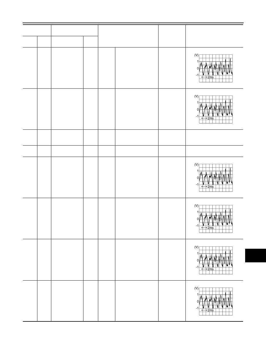
Sound signal rear
RH
Input
Ignition
switch
ON
Sound output
Outputs
waveform
synchronized
with sound.
109
(W)
115
(B)
Sound signal
front RH
Input
Ignition
switch
ON
Sound output
Outputs
waveform
synchronized
with sound.
110
(LG)
20
(B)
BOSE amp. ON
signal
Output
Ignition
switch
ACC
—
7.0 – 16.0 V
12.0 V
111
(GR)
—
Shield
—
—
—
—
—
112
(B)
118
(W)
Sound signal rear
LH
Input
Ignition
switch
ON
Sound output
Outputs
waveform
synchronized
with sound.
113
(R)
119
(G)
Sound signal
front LH
Input
Ignition
switch
ON
Sound output
Outputs
waveform
synchronized
with sound.
120
(R)
124
(B)
Satellite radio
sound signal LH
Input
Ignition
switch
ON
When satellite radio
mode is selected.
Outputs
waveform
synchronized
with sound.
121
(W)
125
(G)
Satellite radio
sound signal RH
Output
Ignition
switch
ON
When satellite radio
mode is selected.
Outputs
waveform
synchronized
with sound.
Terminal
(Wire color)
Description
Condition
Standard
Reference value
(Approx.)
+
–
Signal name
Input/
Output
SKIB3609E
SKIB3609E
SKIB3609E
SKIB3609E
SKIB3609E
SKIB3609E