Nissan Quest E52. Manual - part 1080


  Index      Nissan     Nissan Quest E52 (2011-2014 year) - Service and Repair Manual


Search            


Content   ..  1078  1079  1080  1081   ..


Nissan Quest E52. Manual - part 1080


SEC-10

< SYSTEM DESCRIPTION >

[WITH INTELLIGENT KEY SYSTEM]

SYSTEM

SYSTEM

INTELLIGENT KEY SYSTEM/ENGINE START FUNCTION

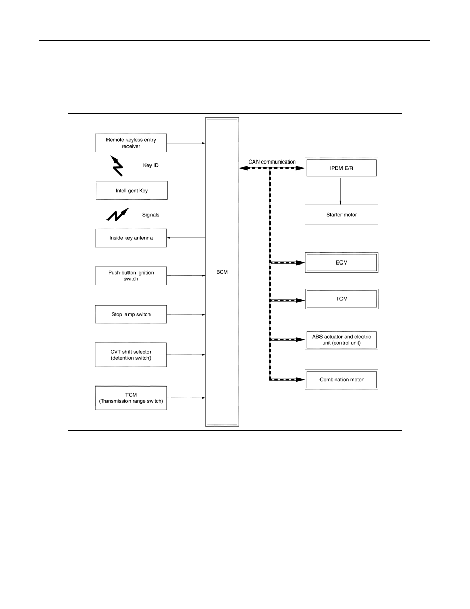
INTELLIGENT KEY SYSTEM/ENGINE START FUNCTION : System Description

INFOID:0000000009650693

SYSTEM DIAGRAM

INPUT/OUTPUT SIGNAL CHART

Input Signal Item

JMKIA8234GB

SYSTEM

SEC-11

< SYSTEM DESCRIPTION >

[WITH INTELLIGENT KEY SYSTEM]

C

D

E

F

G

H

I

J

L

M

A

B

SEC

N

O

P

Output Signal Item

SYSTEM DESCRIPTION 

• The engine start function of Intelligent Key system makes it possible to start and stop the engine without

using the key, based on the electronic ID verification. The electronic ID verification is performed between
BCM and Intelligent Key when the push-button ignition switch is pressed while the Intelligent Key is within
the detection area of inside key antenna.
NOTE:
The driver should carry the Intelligent Key at all times.

• Intelligent Key has 2 IDs [Intelligent Key ID and NVIS (NATS) ID]. It can perform the door lock/unlock opera-

tion and the push-button ignition switch operation when the registered Intelligent Key is carried.

• If the ID is successfully verified, when push-button ignition switch is pressed, the engine can be started.
• Up to 4 Intelligent Keys can be registered (Including the standard Intelligent Key) upon request from the cus-

tomer.
NOTE:
Refer to 

DLK-36, "INTELLIGENT KEY SYSTEM : System Description"

 for any functions other than engine

start function of Intelligent Key system.

PRECAUTIONS FOR INTELLIGENT KEY SYSTEM

The transponder [the chip for NVIS (NATS) ID verification] is integrated into the Intelligent Key. (For the
conventional models, it is integrated into the mechanical key.) Therefore, ID verification cannot be per-
formed by mechanical key only.
In that case, NVIS (NATS) ID verification can be performed when Intelligent Key backside is contacted
to push-button ignition switch while brake pedal is depressed. If verification result is OK, engine can
be started.

OPERATION WHEN INTELLIGENT KEY IS CARRIED

1.

When the push-button ignition switch is pressed, the BCM activates the inside key antenna and transmits
the request signal to the Intelligent Key.

2.

The Intelligent Key receives the request signal and transmits the Intelligent Key ID signal to the BCM.

3.

BCM receives the Intelligent Key ID signal via remote keyless entry receiver and verifies it with the regis-
tered ID.

4.

BCM turns ACC relay ON and transmits the ignition power supply ON signal to IPDM E/R.

Transmit unit

Signal name

ECM

CAN communication

ID verification signal
Engine status signal

IPDM E/R

Push-button ignition switch status signal
Starter relay status signal
Starter control relay signal
Detention switch signal
Interlock/PNP switch signal

Combination meter

Vehicle speed signal (Meter)

ABS actuator and electric unit (control unit)

Vehicle speed signal (ABS)

TCM

Shift position signal

P/N position signal

Remote keyless entry receiver

Key ID signal

Push-button ignition switch

Push-button ignition switch operation signal

Each door switch

Door open/close condition signal

Stop lamp switch

Brake pedal operation signal

CVT shift selector (detention switch)

P position signal

Reception unit

Signal name

Combination meter

CAN communication

Key warning lamp signal

ECM

ID verification signal

Inside key antenna

Key ID request signal

SEC-12

< SYSTEM DESCRIPTION >

[WITH INTELLIGENT KEY SYSTEM]

SYSTEM

5.

IPDM E/R turns the ignition relay ON and starts the ignition power supply.

6.

IPDM E/R turns the starter control relay ON for engine starting in advance.

7.

BCM detects the selector lever position and brake pedal operation condition.

8.

BCM transmits the starter request signal to IPDM E/R and turns the starter relay in IPDM E/R ON if BCM
judges that the engine start condition* is satisfied.

9.

Power supply is supplied through the starter relay and the starter control relay to operate the starter motor.

CAUTION:

If a malfunction is detected in the Intelligent Key system, the “KEY” warning lamp on the combina-
tion meter illuminates. At that time, the engine cannot be started.

10. When BCM receives feedback signal from ECM indicating that the engine is started, the BCM transmits a

stop signal to IPDM E/R and stops cranking by turning OFF the starter relay. (If engine start is unsuccess-
ful, cranking stops automatically within 5 seconds.)

CAUTION:

When the Intelligent Key is carried outside of the vehicle (inside key antenna detection area) while
the power supply is in the ACC or ON position, even if the engine start condition* is satisfied, the
engine cannot be started.

*: For the engine start condition, refer to “IGNITION SWITCH POSITION CHANGE TABLE BY PUSH-BUT-
TON IGNITION SWITCH OPERATION”.

OPERATION RANGE

Engine can be started when Intelligent Key is inside the vehicle. However, sometimes engine may not start
when Intelligent Key is on instrument panel or in glove box.

ENGINE START OPERATION WHEN INTELLIGENT KEY IS CONTACTED TO PUSH-BUTTON IG-
NITION SWITCH

When Intelligent Key battery is discharged, NVIS (NATS) ID verification between transponder in Intelligent Key
and BCM is performed when Intelligent Key backside is contacted to push-button ignition switch while brake
pedal is depressed. If the verification result is OK, engine can be started.

IGNITION SWITCH POSITION CHANGE TABLE BY PUSH-BUTTON IGNITION SWITCH OPERA-
TION

The ignition switch position can be changed by the following operations.
NOTE:
• When an Intelligent Key is within the detection area of inside key antenna or when Intelligent Key backside is

contacted to push-button ignition switch, it is equivalent to the operations below.

• When starting the engine, the BCM monitors under the engine start conditions,

CVT models

- Brake pedal operation condition
- Selector lever position
- Vehicle speed

Vehicle speed: less than 4 km/h (2.5 MPH)

Vehicle speed: 4 km/h (2.5 MPH) or more

Power supply position

Condition

Push-button ignition switch operation 

frequency

Selector lever

Brake pedal operation 

condition

OFF 

 ACC

Not depressed

1

OFF 

 ACC 

 ON

Not depressed

2

OFF 

 ACC 

 ON 

 OFF

Not depressed

3

OFF 

 START

ACC 

 START

ON 

 START

P or N position

Depressed

1

Engine is running 

 OFF

1

SYSTEM

SEC-13

< SYSTEM DESCRIPTION >

[WITH INTELLIGENT KEY SYSTEM]

C

D

E

F

G

H

I

J

L

M

A

B

SEC

N

O

P

Emergency stop operation

• Press and hold the push-button ignition switch for 2 seconds or more.

• Press the push-button ignition switch 3 times or more within 1.5 seconds.

Power supply position

Condition

Push-button ignition switch operation 

frequency

Selector lever

Brake pedal operation 

condition

Engine is running 

 ACC 

Emergency stop operation

Engine stall return operation 
while driving 

N position

Not depressed

1


Content   ..  1078  1079  1080  1081   ..