Content .. 1034 1035 1036 1037 ..
Nissan Quest E52. Manual - part 1036
FRONT LOWER LINK
RSU-15
< REMOVAL AND INSTALLATION >
C
D
F
G
H
I
J
K
L
M
A
B
RSU
N
O
P
FRONT LOWER LINK
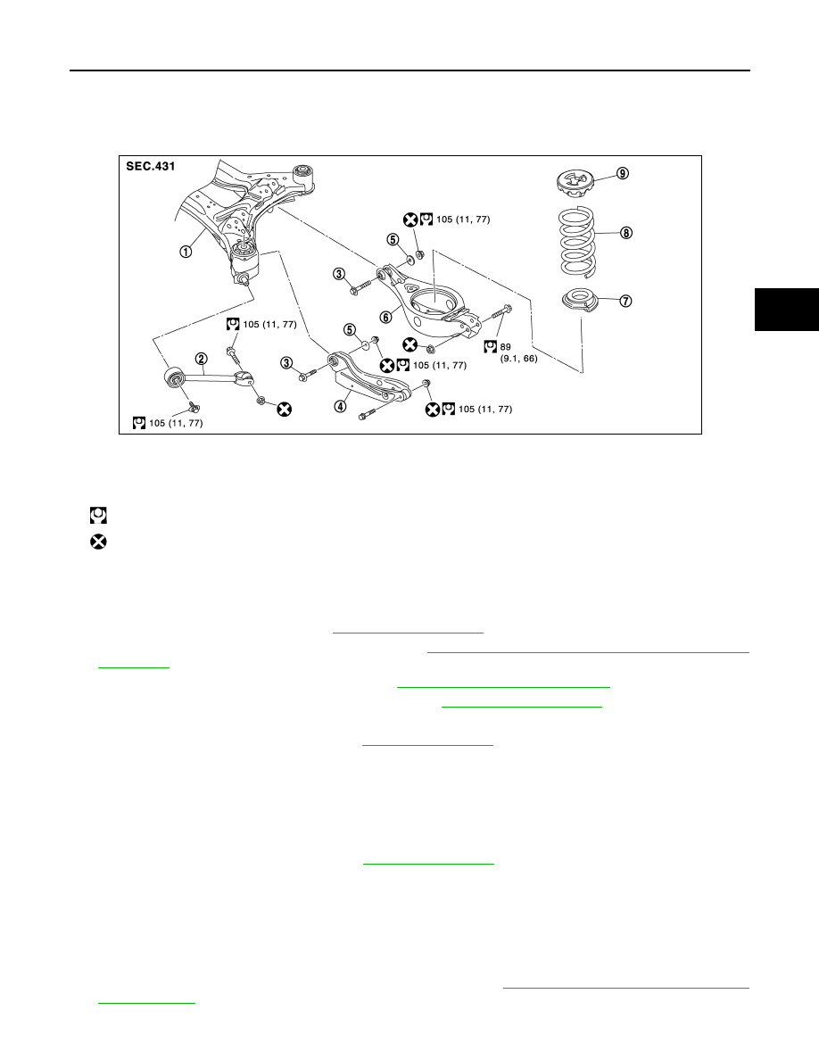
Exploded View
INFOID:0000000009652832
Removal and Installation
INFOID:0000000009652833
REMOVAL
1.
Remove tire with power tool. Refer to
.
2.
Remove wheel sensor and sensor harness. Refer to
BRC-120, "REAR WHEEL SENSOR : Removal and
.
3.
Remove rear lower link and coil spring. Refer to
RSU-8, "Removal and Installation"
4.
Separate shock absorber from front lower link. Refer to
5.
Remove eccentric disc, adjusting bolt, mounting bolt, and nut, then remove front lower link.
6.
Perform inspection after removal. Refer to
INSTALLATION
Note the following, and install in the reverse order of removal.
• Install adjusting bolt so that the graduation marks on adjusting bolt are positioned downward.
• Perform final tightening of fixing parts at the vehicle installation position (rubber bushing), under unladen
conditions with tires on level ground.
• Never reuse front lower link mounting nut.
• Perform inspection after installation. Refer to
Inspection
INFOID:0000000009652834
INSPECTION AFTER REMOVAL
Check front lower link and bushing for any deformation, cracks, or damage. Replace it if necessary.
INSPECTION AFTER INSTALLATION
1.
Check wheel sensor harness for proper connection. Refer to
.
1.
Rear suspension member
2.
Radius rod
3.
Adjusting bolt
4.
Front lower link
5.
Eccentric disk
6.
Rear lower link
7.
Rubber seat
8.
Coil spring
9.
Upper seat
: N·m (kg-m, ft-lb)
: Always replace after every disassembly.
JSEIA0397GB