Nissan Quest E52. Manual - part 87
AV
AUX IMAGE SIGNAL CIRCUIT
AV-227
< DTC/CIRCUIT DIAGNOSIS >
[BASE AUDIO WITH SEPARATE DISPLAY]
C
D
E
F
G
H
I
J
K
L
M
B
A
O
P
AUX IMAGE SIGNAL CIRCUIT
Description
INFOID:0000000009652064
• Transmits the image signal of AUX (auxiliary input) device from auxiliary input jacks to AV control unit.
• The AV control unit transmits the AUX image signal to the front display unit by composite image signal.
Diagnosis Procedure
INFOID:0000000009652065
1.
CHECK CONTINUITY AUX IMAGE SIGNAL CIRCUIT
1.
Turn ignition switch OFF.
2.
Disconnect AV control unit connector and auxiliary input jacks connector.
3.
Check continuity between AV control unit harness connector and auxiliary input jacks harness connector.
4.
Check continuity between AV control unit harness connector and ground.
Is the inspection result normal?
YES
>> GO TO 2.
NO
>> Repair harness or connector.
2.
CHECK AUX IMAGE SIGNAL
1.
Connect AV control unit connector and auxiliary input jacks connector.
2.
Turn ignition switch ON.
3.
Check signal between AV control unit harness connector and ground.
Is the inspection result normal?
YES
>> Replace AV control unit. Refer to
AV-250, "Removal and Installation"
.
NO
>> Check that there is no malfunction in the external device.
AV control unit
Auxiliary input jacks
Continuity
Connector
Terminal
Connector
Terminal
M173
61
B273
7
Existed
69
8
AV control unit
Ground
Continuity
Connector
Terminal
M173
61
Not existed
69
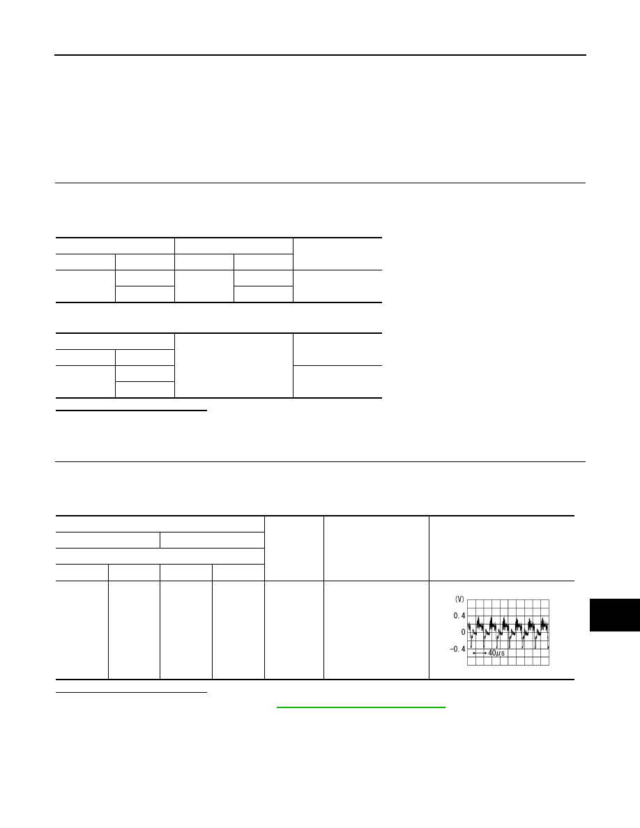
Probe
Condition
Standard
Reference value
(+)
(
−
)
AV control unit
Connector
Terminal
Connector
Terminal
M173
61
M173
69
When AUX
image is dis-
played on
front or rear
display unit.
Waveform according to
AUX image is input.
SKIB2251J