Nissan Quest E52. Manual - part 85


  Index      Nissan     Nissan Quest E52 (2011-2014 year) - Service and Repair Manual


Search            


Content   ..  83  84  85  86   ..


Nissan Quest E52. Manual - part 85


AV

RGB (G: GREEN) SIGNAL CIRCUIT

AV-219

< DTC/CIRCUIT DIAGNOSIS >

[BASE AUDIO WITH SEPARATE DISPLAY]

C

D

E

F

G

H

I

J

K

L

M

B

A

O

P

RGB (G: GREEN) SIGNAL CIRCUIT

Description

INFOID:0000000009652048

Transmit the image displayed with AV control unit with RGB signal to the front display unit.

Diagnosis Procedure

INFOID:0000000009652049

1.

CHECK CONTINUITY RGB (G: GREEN) SIGNAL CIRCUIT

1.

Turn ignition switch OFF.

2.

Disconnect front display unit connector and AV control unit connector.

3.

Check continuity between front display unit harness connector and AV control unit harness connector.

4.

Check continuity between front display unit harness connector and ground.

Is the inspection result normal?

YES

>> GO TO 2.

NO

>> Repair harness or connector.

2.

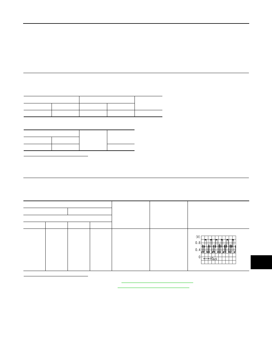
CHECK RGB (G: GREEN) SIGNAL

1.

Connect front display unit connector and AV control unit connector.

2.

Turn ignition switch ON.

3.

Check signal between front display unit harness connector and ground.

Is the inspection result normal?

YES

>> Replace front display unit. Refer to 

AV-251, "Removal and Installation"

.

NO

>> Replace AV control unit. Refer to 

AV-250, "Removal and Installation"

.

Front display unit

AV control unit

Continuity

Connector

Terminal

Connector

Terminal

M156

6

M172

44

Existed

Front display unit

Ground

Continuity

Connector

Terminal

M156

6

Not existed

Probe

Condition

Standard

Reference value

(+)

(-)

Front display unit

Connector

Terminal

Connector

Terminal

M156

6

M156

1

Start confirmation/
adjustment mode, 
and then display col-
or bar by selecting 
“Color Spectrum 
Bar” on DISPLAY 
DIAGNOSIS 
screen.

Waveform accord-
ing to RGB image is 
input.

JSNIA1030ZZ

AV-220

< DTC/CIRCUIT DIAGNOSIS >

[BASE AUDIO WITH SEPARATE DISPLAY]

RGB (B: BLUE) SIGNAL CIRCUIT

RGB (B: BLUE) SIGNAL CIRCUIT

Description

INFOID:0000000009652050

Transmit the image displayed with AV control unit with RGB signal to the front display unit.

Diagnosis Procedure

INFOID:0000000009652051

1.

CHECK CONTINUITY RGB (B: BLUE) SIGNAL CIRCUIT

1.

Turn ignition switch OFF.

2.

Disconnect front display unit connector and AV control unit connector.

3.

Check continuity between front display unit harness connector and AV control unit harness connector.

4.

Check continuity between front display unit harness connector and ground.

Is the inspection result normal?

YES

>> GO TO 2.

NO

>> Repair harness or connector.

2.

CHECK RGB (B: BLUE) SIGNAL

1.

Connect front display unit connector and AV control unit connector.

2.

Turn ignition switch ON.

3.

Check signal between front display unit harness connector and ground.

Is the inspection result normal?

YES

>>  Replace front display unit. Refer to 

AV-251, "Removal and Installation"

.

NO

>> Replace AV control unit. Refer to 

AV-250, "Removal and Installation"

.

Front display unit

AV control unit

Continuity

Connector

Terminal

Connector

Terminal

M156

18

M172

45

Existed

Front display unit

Ground

Continuity

Connector

Terminal

M156

18

Not existed

Probe

Condition

Standard

Reference value

(+)

(-)

Front display unit

Connector

Terminal

Connector

Terminal

M156

18

M156

1

Start confirmation/
adjustment mode, 
and then display col-
or bar by selecting 
“Color Spectrum 
Bar” on DISPLAY 
DIAGNOSIS 
screen.

Waveform accord-
ing to RGB image is 
input.

JSNIA1031ZZ

AV

RGB SYNCHRONIZING SIGNAL CIRCUIT

AV-221

< DTC/CIRCUIT DIAGNOSIS >

[BASE AUDIO WITH SEPARATE DISPLAY]

C

D

E

F

G

H

I

J

K

L

M

B

A

O

P

RGB SYNCHRONIZING SIGNAL CIRCUIT

Description

INFOID:0000000009652052

Transmit the RGB synchronizing signal to the front display unit so as to synchronize the RGB image displayed
with AV control unit.

Diagnosis Procedure

INFOID:0000000009652053

1.

CHECK CONTINUITY RGB SYNCHRONIZING SIGNAL CIRCUIT

1.

Turn ignition switch OFF.

2.

Disconnect front display unit connector and AV control unit connector.

3.

Check continuity between front display unit harness connector and AV control unit harness connector.

4.

Check continuity between front display unit harness connector and ground.

Is the inspection result normal?

YES

>> GO TO 2.

NO

>> Repair harness or connector.

2.

CHECK RGB SYNCHRONIZING SIGNAL

1.

Connect front display unit connector and AV control unit connector.

2.

Turn ignition switch ON.

3.

Check signal between front display unit harness connector and ground.

Is the inspection result normal?

YES

>> Replace front display unit. Refer to 

AV-251, "Removal and Installation"

.

NO

>> Replace AV control unit. Refer to 

AV-250, "Removal and Installation"

.

Front display unit

AV control unit

Continuity

Connector

Terminal

Connector

Terminal

M156

19

M172

42

Existed

Front display unit

Ground

Continuity

Connector

Terminal

M156

19

Not existed

Probe

Standard

Reference value

(+)

(-)

Front display unit

Connector

Terminal

Connector

Terminal

M156

19

M156

1

Waveform of 0.8 V - 5.5 
V is input.

SKIB3603E

AV-222

< DTC/CIRCUIT DIAGNOSIS >

[BASE AUDIO WITH SEPARATE DISPLAY]

RGB AREA (YS) SIGNAL CIRCUIT

RGB AREA (YS) SIGNAL CIRCUIT

Description

INFOID:0000000009652054

Transmits the display area of RGB image displayed by AV control unit with RGB area (YS) signal to front dis-
play unit.

Diagnosis Procedure

INFOID:0000000009652055

1.

CHECK CONTINUITY RGB AREA (YS) SIGNAL CIRCUIT

1.

Turn ignition switch OFF.

2.

Disconnect front display unit connector and AV control unit connector.

3.

Check continuity between front display unit harness connector and AV control unit harness connector.

4.

Check continuity between front display unit harness connector and ground.

Is the inspection result normal?

YES

>> GO TO 2.

NO

>> Repair harness or connector.

2.

CHECK RGB AREA (YS) SIGNAL

1.

Connect front display unit connector and AV control unit connector.

2.

Turn ignition switch ON.

3.

Check signal between front display unit harness connector and ground.

Is the inspection result normal?

YES

>> Replace front display unit. Refer to 

AV-251, "Removal and Installation"

.

NO

>> Replace AV control unit. Refer to 

AV-250, "Removal and Installation"

.

Front display unit

AV control unit

Continuity

Connector

Terminal

Connector

Terminal

M156

9

M172

40

Existed

Front display unit

Ground

Continuity

Connector

Terminal

M156

9

Not existed

Probe

Condition

Standard

Reference value

(+)

(-)

Front display unit

Connector

Terminal

Connector

Terminal

M156

9

M156

1

At RGB image is dis-
played

5.5 V or less

5.0 V

At AUX image is dis-
played

Waveform of 0.8 V - 
5.5 V is input.

PKIB4948J


Content   ..  83  84  85  86   ..