Nissan Quest E52. Manual - part 63
AV
COMPONENT PARTS
AV-131
< SYSTEM DESCRIPTION >
[BASE AUDIO WITH SEPARATE DISPLAY]
C
D
E
F
G
H
I
J
K
L
M
B
A
O
P
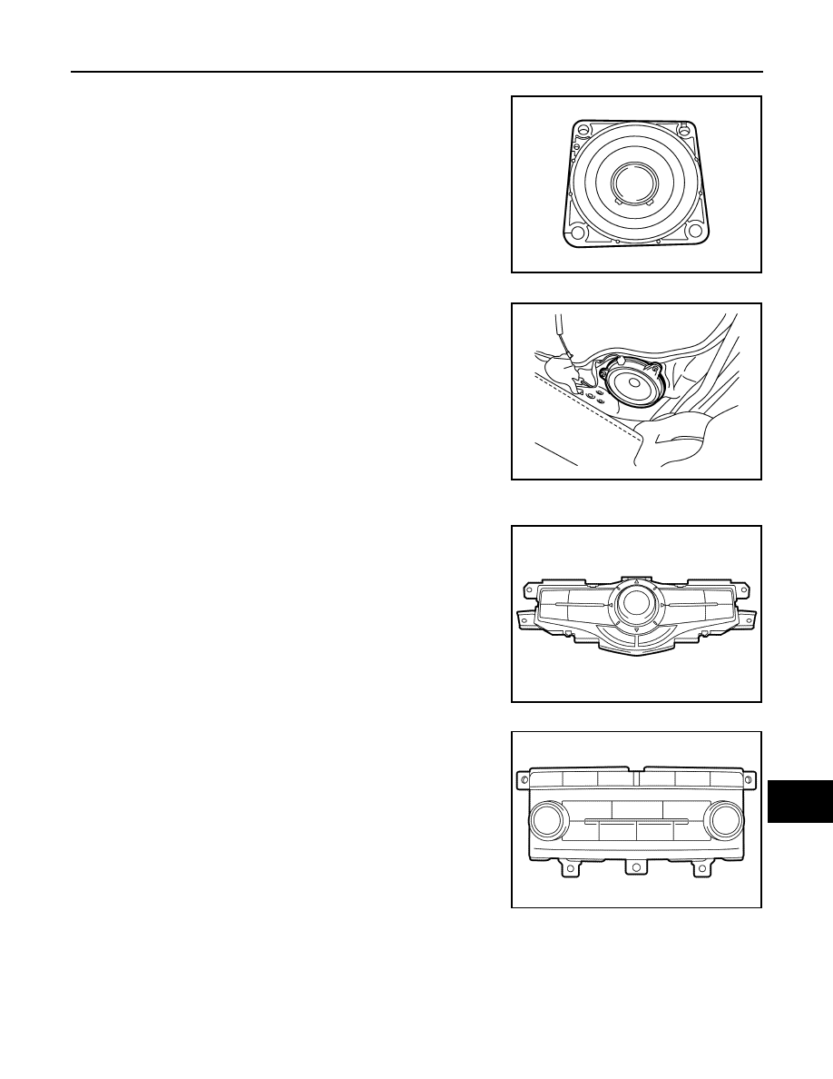
FRONT SQUAWKER
•
φ
6.5 cm (2 in) squawker is installed to the side of instrument
panel.
• Sound signal is input from the AV control unit to output high and
mid range sounds.
SLIDE DOOR SPEAKER
•
φ
16cm (6.5 in) speaker is located at the lower part of the back of
the slide door.
• Sound signal is input from the AV control unit to output high, mid,
and low range sounds.
Multifunction Switch
INFOID:0000000009651992
• The multifunction switch is an integrated switch that combines the
audio operation and other operations switches. This integrated
switch is located in the lower part of the front display unit.
• Connected with preset switch via hardwire and operation signal is
transmitted to AV control unit via AV communication.
PRESET SWITCH
• The preset switch is separated from the multifunction switch and
capable of audio operation.
• Operation signals of the multifunction switch and the preset switch
are transmitted to the AV control unit via AV communication.
Rated input
: 7 W
Maximum
input
: 40 W
Impedance
: 4
Ω
JSNIA3402ZZ
Rated input
: 20 W
Maximum
input
: 40 W
Impedance
: 2
Ω
JSNIA3405ZZ
JSNIA4202ZZ
JSNIA4203ZZ