Nissan Quest E52. Manual - part 55
AV
STEERING SWITCH SIGNAL B CIRCUIT (STEERING SWITCH TO TEL ADAPT-
ER UNIT)
AV-99
< DTC/CIRCUIT DIAGNOSIS >
[DISPLAY AUDIO]
C
D
E
F
G
H
I
J
K
L
M
B
A
O
P
STEERING SWITCH SIGNAL B CIRCUIT (STEERING SWITCH TO TEL
ADAPTER UNIT)
Description
INFOID:0000000009651952
• Transmits the steering switch signal to TEL adapter unit.
• Transmits the steering switch signal to audio unit via TEL adapter unit.
Diagnosis Procedure
INFOID:0000000009651953
1.
CHECK STEERING SWITCH SIGNAL B (STEERING SWITCH TO TEL ADAPTER UNIT) CIRCUIT
1.
Turn ignition switch OFF.
2.
Disconnect TEL adapter unit connector and spiral cable connector.
3.
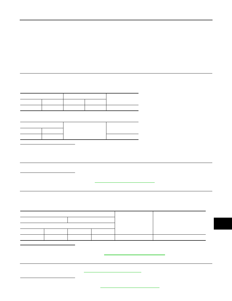
Check continuity between TEL adapter unit harness connector and spiral cable harness connector.
4.
Check continuity between TEL adapter unit harness connector and ground.
Is the inspection result normal?
YES
>> GO TO 2.
NO
>> Repair harness or connector.
2.
CHECK SPIRAL CABLE
Check spiral cable.
Is the inspection result normal?
YES
>> GO TO 3.
NO
>> Replace spiral cable. Refer to
SR-15, "Removal and Installation"
3.
CHECK TEL ADAPTER UNIT VOLTAGE
1.
Connect TEL adapter unit connector and spiral cable connector.
2.
Turn ignition switch ON.
3.
Check voltage between TEL adapter unit harness connector.
Is the inspection result normal?
YES
>> GO TO 4.
NO
>> Replace TEL adapter unit. Refer to
AV-118, "Removal and Installation"
4.
CHECK STEERING SWITCH
1.
Turn ignition switch OFF.
2.
Check steering switch. Refer to
AV-100, "Component Inspection"
Is the inspection result normal?
YES
>> INSPECTION END
NO
>> Replace steering wheel. Refer to
ST-12, "Removal and Installation"
TEL adapter unit
Spiral cable
Continuity
Connector
Terminal
Connector
Terminal
M138
13
M33
31
Existed
TEL adapter unit
Ground
Continuity
Connector
Terminal
M138
13
Not existed
Probe
Standard
Voltage
(Approx.)
(+)
(
−
)
TEL adapter unit
Connector
Terminal
Connector
Terminal
M138
13
M138
14
0 - 5.25 V
5.0 V