Nissan Quest E52. Manual - part 26


  Index      Nissan     Nissan Quest E52 (2011-2014 year) - Service and Repair Manual


Search            


Content   ..  24  25  26  27   ..


Nissan Quest E52. Manual - part 26


DOOR MIRROR MOTOR

ADP-97

< DTC/CIRCUIT DIAGNOSIS >

C

D

E

F

G

H

I

K

L

M

A

B

ADP

N

O

P

Is the inspection result normal?

YES

>> INSPECTION END

NO

>> Replace door mirror motor.
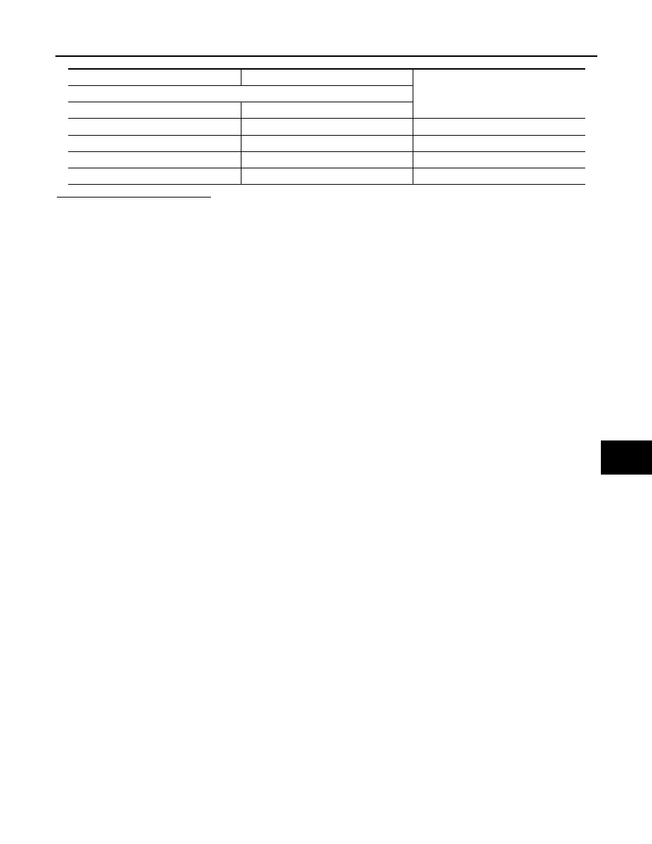
Door mirror

Operational direction

Terminal

(+)

(-)

10

11

RIGHT

11

10

LEFT

12

10

UP

10

12

DOWN

ADP-98

< DTC/CIRCUIT DIAGNOSIS >

SEAT MEMORY INDICATOR

SEAT MEMORY INDICATOR

Component Function Check

INFOID:0000000009649689

1.

CHECK FUNCTION

1.

Select “MEMORY SW INDCTR” in “Active test” mode with CONSULT. 

2.

Check the memory indicator operation.

Is the operation of relevant parts normal?

YES

>> INSPECTION END

NO

>> Refer to 

ADP-98, "Diagnosis Procedure"

.

Diagnosis Procedure

INFOID:0000000009649690

1.

CHECK SEAT MEMORY SWITCH INDICATOR OPERATION

Check seat memory switch indicator operation.
Which is the malfunctioning indicator?

All indicators are NG>>GO TO 2.
An indicator is NG>>GO TO 4.

2.

CHECK FUSE

1.

Turn ignition switch OFF.

2.

Check that the following fuse is not fusing.

Is the inspection result normal?

YES

>> GO TO 3.

NO

>> Replace the blown fuse after repairing affected circuit.

3.

CHECK SEAT MEMORY SWITCH INDICATOR POWER SUPPLY

Check voltage between seat memory switch harness connector and ground.

Is the inspection result normal?

YES

>> Replace seat memory switch. Refer to 

ADP-113, "Removal and Installation"

.

NO

>> Repair or replace harness between seat memory switch and 10 A fuse [No.10, located in fuse

block (J/B)].

4.

CHECK SEAT MEMORY SWITCH INDICATOR CIRCUIT

1.

Turn ignition switch OFF.

2.

Disconnect driver seat control unit and seat memory switch connector.

3.

Check continuity between driver seat control unit harness connector and seat memory switch harness
connector.

Test item

Description

MEMORY SW INDCTR

OFF

Memory switch indicator

OFF

ON-1

Indicator 1: ON

ON-2

Indicator 2: ON

Signal name

Fuse No.

Battery power supply

10 (10 A)

(+)

(-)

Voltage (V)

Seat memory switch

Connector

Terminals

D13

5

Ground

Battery voltage

SEAT MEMORY INDICATOR

ADP-99

< DTC/CIRCUIT DIAGNOSIS >

C

D

E

F

G

H

I

K

L

M

A

B

ADP

N

O

P

4.

Check continuity between driver seat control unit harness connector and ground.

Is the inspection result normal?

YES

>> Replace driver seat control unit. Refer to 

ADP-111, "Removal and Installation"

.

NO

>> Repair or replace harness or connector.

Driver seat control unit

Seat memory switch

Continuity

Connector

Terminal

Connector

Terminal

B552

7

D13

7

Existed

23

6

Driver seat control unit

Ground

Continuity 

Connector

Terminal

B552

7

Not existed

23

ADP-100

< SYMPTOM DIAGNOSIS >

MANUAL FUNCTION DOES NOT OPERATE

SYMPTOM DIAGNOSIS

MANUAL FUNCTION DOES NOT OPERATE

ALL COMPONENT

ALL COMPONENT : Diagnosis Procedure

INFOID:0000000009649691

1.

CHECK DRIVER SEAT CONTROL UNIT POWER SUPPLY AND GROUND CIRCUIT

Check driver seat control unit power supply and ground circuit.
Refer to 

ADP-58, "DRIVER SEAT CONTROL UNIT : Diagnosis Procedure"

.

Is the inspection result normal?

YES

>> GO TO 2.

NO

>> Repair or replace the malfunction parts.

2.

CHECK AUTOMATIC DRIVE POSITIONER CONTROL UNIT POWER SUPPLY AND GROUND CIRCUIT

Check automatic drive positioner control unit power supply and ground circuit.
Refer to 

ADP-58, "AUTOMATIC DRIVE POSITIONER CONTROL UNIT : Diagnosis Procedure"

.

Is the inspection result normal?

YES

>> GO TO 3.

NO

>> Repair or replace the malfunction parts.

3.

CONFIRM THE OPERATION

Confirm the operation again.

Is the result normal?

YES

>> Check intermittent incident. Refer to 

GI-42, "Intermittent Incident"

.

NO

>> GO TO 1.

POWER SEAT

POWER SEAT : Diagnosis Procedure

INFOID:0000000009649692

1.

CHECK POWER SEAT SWITCH GROUND CIRCUIT

Check power seat switch ground circuit.
Refer to 

ADP-74, "Diagnosis Procedure"

.

Is the inspection result normal?

YES

>> GO TO 2.

NO

>> Repair or replace harness or connector.

2.

CONFIRM THE OPERATION

Confirm the operation again.
Is the result normal?

YES

>> Check intermittent incident. Refer to 

GI-42, "Intermittent Incident"

.

NO

>> GO TO 1.

SEAT SLIDING

SEAT SLIDING : Diagnosis Procedure

INFOID:0000000009649693

1.

CHECK SLIDING MECHANISM

Check for the following.
• Mechanism deformation or pinched foreign materials.
• Interference with other parts because of poor installation.

Is the inspection result normal?

YES

>> GO TO 2.

NO

>> Repair or replace the malfunction parts.

2.

CHECK SLIDING SWITCH


Content   ..  24  25  26  27   ..