Nissan Cube. Manual - part 966


  Index      Nissan     Nissan Cube (2014 year) - Service and Repair Manual


Search            


Content   ..  964  965  966  967   ..


Nissan Cube. Manual - part 966


TM-120

< DTC/CIRCUIT DIAGNOSIS >

[CVT: RE0F08B]

P0720 OUTPUT SPEED SENSOR

Is the inspection result normal?

YES

>> GO TO 2.

NO

>> GO TO 5.

2.

CHECK TCM INPUT SIGNAL

1.

Turn ignition switch OFF.

2.

Connect secondary speed sensor connector.

3.

Lift the vehicle.

4.

Start the engine.

5.

Check frequency of secondary speed sensor.

Is the inspection result normal?

YES

>> GO TO 8.

NO

>> GO TO 3.

3.

CHECK HARNESS BETWEEN TCM AND SECONDARY SPEED SENSOR (PART 1)

1.

Turn ignition switch OFF.

2.

Disconnect TCM connector and secondary speed sensor connector.

3.

Check continuity between TCM vehicle side harness connector terminals and secondary speed sensor
vehicle side harness connector terminals.

Is the inspection result normal?

YES

>> GO TO 4.

NO

>> Repair or replace damaged parts.

4.

CHECK HARNESS BETWEEN TCM AND SECONDARY SPEED SENSOR (PART 2)

Check continuity between TCM vehicle side harness connector terminals and ground.

Is the inspection result normal?

YES

>> GO TO 8.

NO

>> Repair or replace damaged parts.

Secondary speed sensor vehicle side harness connector

Ground

Voltage (Approx.)

Connector

Terminal

F19

3

Battery voltage

TCM connector

Condition

Data (Approx.) 

Connector

Terminal

E19

29

42

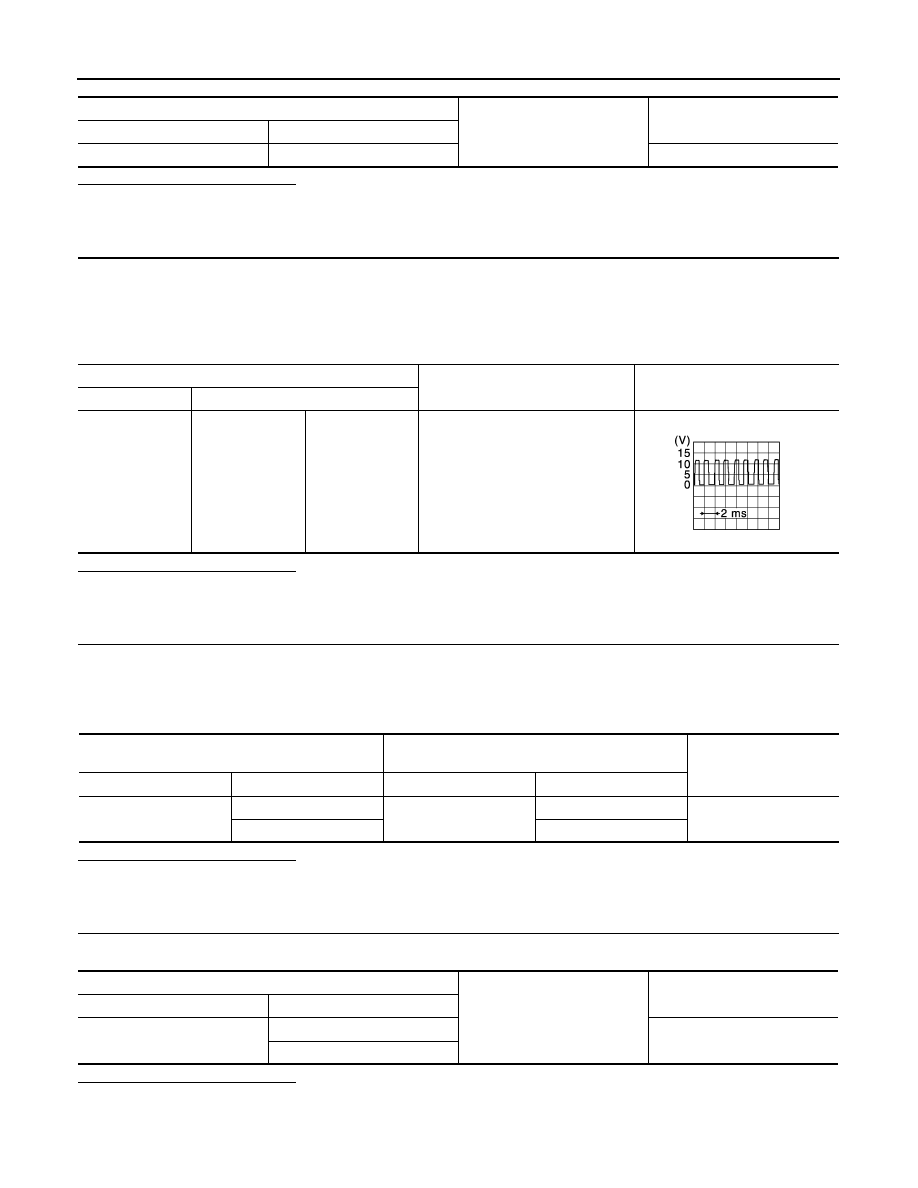
• Selector lever: “L” position
• While driving at 20 km/h (12 MPH)

570 Hz

JSDIA1305GB

TCM vehicle side harness connector

Secondary speed sensor vehicle side harness con-

nector

Continuity

Connector

Terminal

Connector

Terminal

E19

29

F19

2

Existed

42

1

TCM vehicle side harness connector

Ground

Continuity

Connector

Terminal

E19

29

Not existed

42

P0720 OUTPUT SPEED SENSOR

TM-121

< DTC/CIRCUIT DIAGNOSIS >

[CVT: RE0F08B]

C

E

F

G

H

I

J

K

L

M

A

B

TM

N

O

P

5.

CHECK HARNESS BETWEEN SECONDARY SPEED SENSOR (POWER) AND IPDM E/R (PART 1)

1.

Turn ignition switch OFF.

2.

Disconnect IPDM E/R connector.

3.

Check continuity between secondary speed sensor vehicle side harness connector terminal and IPDM E/
R vehicle side harness connector terminal.

Is the inspection result normal?

YES

>> GO TO 6.

NO

>> Repair or replace damaged parts.

6.

CHECK HARNESS BETWEEN SECONDARY SPEED SENSOR (POWER) AND IPDM E/R (PART 2)

Check continuity between secondary speed sensor vehicle side harness connector terminal and ground.

Is the inspection result normal?

YES

>> GO TO 7.

NO

>> Repair or replace damaged parts.

7.

DETECT MALFUNCTIONING ITEMS

Check the following.
• IPDM E/R
• 10A fuse (No.55, located in the IPDM E/R)
• Harness for short or open between IPDM E/R and ignition switch (Refer to 

PG-33, "Wiring Diagram - IGNI-

TION POWER SUPPLY -"

.)

• Ignition switch

Is the inspection result normal?

YES

>> Check intermittent incident. Refer to 

GI-40, "Intermittent Incident"

.

NO

>> Repair or replace damaged parts.

8.

CHECK INTERMITTENT INCIDENT

Refer to 

GI-40, "Intermittent Incident"

.

Is the inspection result normal?

YES

>> Replace secondary speed sensor. Refer to 

TM-228, "Exploded View"

.

NO

>> Repair or replace damaged parts.

Secondary speed sensor vehicle side harness con-

nector

IPDM E/R vehicle side harness connector

Continuity

Connector

Terminal

Connector

Terminal

F19

3

E15

58

Existed

Secondary speed sensor vehicle side harness connector

Ground

Continuity

Connector

Terminal

F19

3

Not existed

TM-122

< DTC/CIRCUIT DIAGNOSIS >

[CVT: RE0F08B]

P0725 ENGINE SPEED

P0725 ENGINE SPEED

Description

INFOID:0000000009948971

TCM receives engine speed signal from ECM via CAN communication.

DTC Logic

INFOID:0000000009948972

DTC DETECTION LOGIC

DTC CONFIRMATION PROCEDURE

CAUTION:

Always drive vehicle at a safe speed.

1.

PRECONDITIONING

Immediately after performing any “DTC CONFIRMATION PROCEDURE”, always turn ignition switch OFF.
Then wait at least 10 seconds before performing the next test.

>> GO TO 2.

2.

PERFORM DTC CONFIRMATION PROCEDURE

With CONSULT

1.

Start the engine.

2.

Select “Data Monitor” in “TRANSMISSION”.

3.

Select “PRI SPEED SEN”.

4.

Drive the vehicle.

5.

Maintain the following conditions for 10 seconds or more.

6.

Stop the vehicle.

7.

Select “Self Diagnostic Results” in “TRANSMISSION”.

Is “P0725” detected?

YES

>> Go to 

TM-122, "Diagnosis Procedure"

.

NO

>> INSPECTION END

Diagnosis Procedure

INFOID:0000000009948973

1.

CHECK DTC WITH ECM

With CONSULT

1.

Turn ignition switch ON.

2.

Perform “Self Diagnostic Results” in “ENGINE”.

Is the inspection result normal?

YES

>> Check intermittent incident. Refer to 

GI-40, "Intermittent Incident"

.

NO

>> Check DTC detected item. Refer to 

TM-186, "DTC Index"

.

DTC

Trouble diagnosis name

DTC is detected if...

Possible cause

P0725

Engine Speed Input Circuit

• TCM detects a malfunction in CAN com-

munication between TCM and ECM

• When primary pulley speed is more than 

1,000 rpm, engine speed (CAN signal) is 
less than 450 rpm

• Harness or connectors

(CAN communication line is open or 
shorted.)
(Engine speed signal circuit is open or 
shorted.)

• ECM

PRI SPEED SEN

: More than 1,000 rpm

P0740 TORQUE CONVERTER

TM-123

< DTC/CIRCUIT DIAGNOSIS >

[CVT: RE0F08B]

C

E

F

G

H

I

J

K

L

M

A

B

TM

N

O

P

P0740 TORQUE CONVERTER

Description

INFOID:0000000009948974

• Torque converter clutch solenoid valve is installed to control valve.
• Torque converter clutch solenoid valve adjusts oil pump discharge pressure to an optimum level according to

the driving conditions.

• The adoption of an N/L type (normal low) torque converter clutch solenoid valve enables generation of a

control oil pressure when a voltage is not applied to the coil.

• Torque converter clutch solenoid valve is controlled by TCM according to signals transmitted from vehicle

speed sensor and accelerator pedal position sensor.

• Lock-up is prohibited when CVT fluid temperature is low.
• When accelerator pedal is depressed (throttle opening angle is less than 2.0/8) in the lock-up state, engine

speed does not suddenly change. If engine speed changes suddenly, lock-up is not applied.

DTC Logic

INFOID:0000000009948975

DTC DETECTION LOGIC

DTC CONFIRMATION PROCEDURE

CAUTION:

Always drive vehicle at a safe speed.

1.

PRECONDITIONING (PART 1)

Immediately after performing any “DTC CONFIRMATION PROCEDURE”, always turn ignition switch OFF.
Then wait at least 10 seconds before performing the next test.

>> GO TO 2.

2.

PRECONDITIONING (PART 2)

With CONSULT

1.

Start the engine.

2.

Select “Data Monitor” in “TRANSMISSION”.

3.

Select “ATF TEMP SEN”.

Is “ATF TEMP SEN” value 2.17 V or less?

YES

>> GO TO 3.

NO

>> 1.

Warm up transaxle.

2.

GO TO 3.

3.

PERFORM DTC CONFIRMATION PROCEDURE

With CONSULT

1.

Start the engine.

2.

Select “Data Monitor” in “TRANSMISSION”.

3.

Select “VEHICLE SPEED”.

4.

Drive the vehicle.

5.

Maintain the following conditions for 5 seconds or more.

6.

Stop the vehicle.

DTC

Trouble diagnosis name

DTC is detected if...

Possible cause

P0740

Torque Converter Clutch Cir-
cuit/Open

• Torque converter clutch solenoid valve 

monitor voltage value of TCM is less than 
70% of torque converter clutch solenoid 
valve target voltage value

• Torque converter clutch solenoid valve 

current command value of TCM and 
torque converter clutch solenoid valve 
current monitor value is deviated

• Harness or connectors

(Torque converter clutch solenoid valve 
circuit is open or shorted.)

• Torque converter clutch solenoid valve

VEHICLE SPEED

: More than 40 km/h (25 MPH)


Content   ..  964  965  966  967   ..