Nissan Cube. Manual - part 949
TM-52
< UNIT DISASSEMBLY AND ASSEMBLY >
[6MT: RS6F94R]
MAINSHAFT AND GEAR
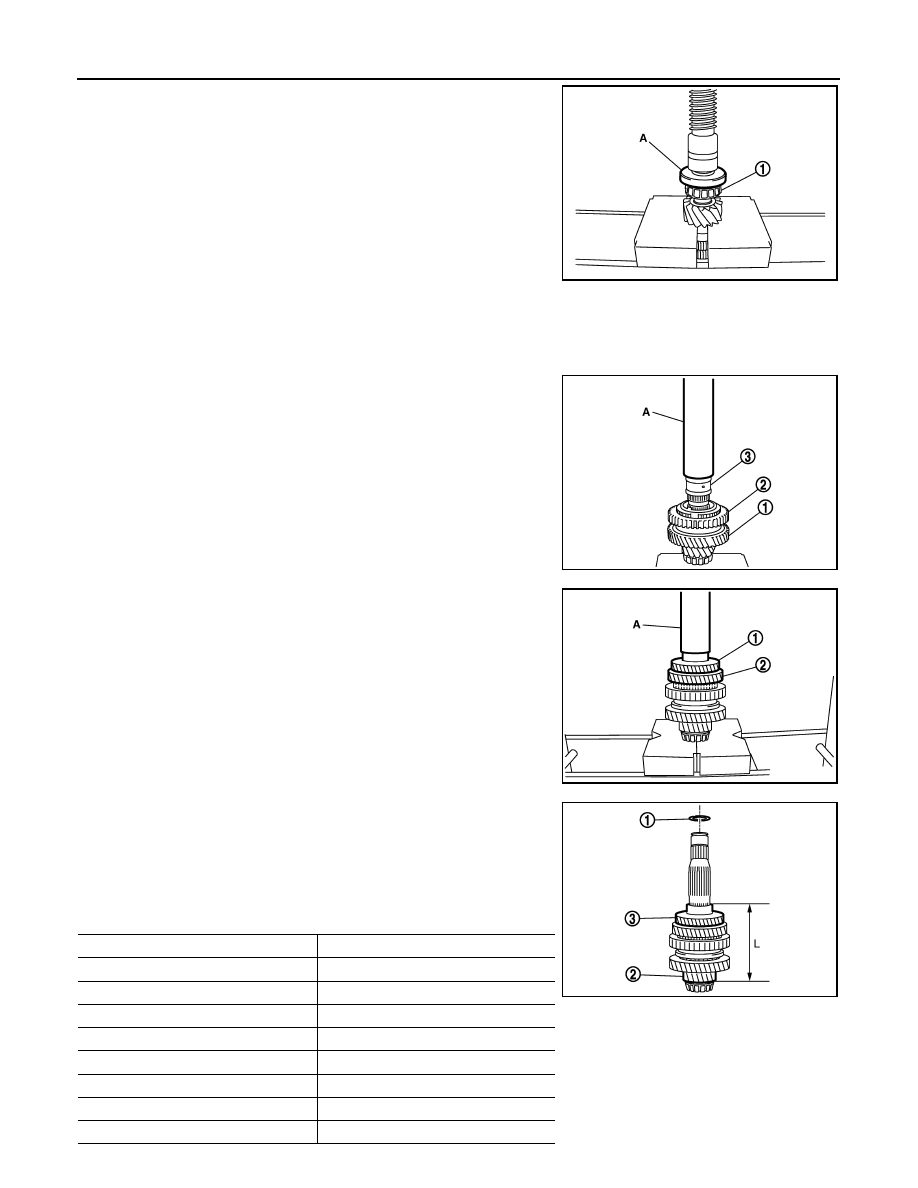
1.
Install mainshaft front bearing inner race (1), using the drift (A)
[SST: ST36720030 ( - )].
CAUTION:
Replace mainshaft front bearing outer race and mainshaft
front bearing inner race as a set.
2.
Apply gear oil to 1st inner baulk ring, 1st synchronizer cone, 1st
outer baulk ring, 2nd inner baulk ring, 2nd synchronizer cone,
and 2nd outer baulk ring.
CAUTION:
• Replace 1st inner baulk ring, 1st synchronizer cone, and
1st outer baulk ring as a set.
• Replace 2nd inner baulk ring, 2nd synchronizer cone, and
2nd outer baulk ring as a set.
3.
Install insert keys and 1st-2nd coupling sleeve to 1st-2nd synchronizer hub.
CAUTION:
Replace 1st-2nd synchronizer hub and 1st-2nd coupling sleeve as a set.
4.
Install 1st main gear (1), 1st inner baulk ring, 1st synchronizer
cone, 1st outer baulk ring, 1st-2nd synchronizer hub assembly
(2), 2nd inner baulk ring, 2nd synchronizer cone, and 2nd outer
baulk ring.
5.
Install bushing (3), using the drift (A) [SST: KV32102700 ( - )].
6.
Install 3rd main gear (1) and 2nd main gear (2), using the drift
(A) [SST: KV32102700 ( - )].
7.
Measure dimension “L” as shown in the figure. Select mainshaft
adjusting shim (1) according to the following list, and then install
it to mainshaft.
Unit: mm (in)
PCIB1733E
PCIB1734E
PCIB1735E
2
: Mainshaft
3
: 3rd main gear
Dimension “L”
Thickness of mainshaft adjusting shim
147.690 – 147.666 (5.815 – 5.814)
1.500 (0.0591)
147.665 – 147.641 (5.814 – 5.813)
1.525 (0.0600)
147.640 – 147.616 (5.813 – 5.812)
1.550 (0.0610)
147.615 – 147.591 (5.812 – 5.811)
1.575 (0.0620)
147.590 – 147.566 (5.811 – 5.810)
1.600 (0.0630)
147.565 – 147.541 (5.810 – 5.809)
1.625 (0.0640)
147.540 – 147.516 (5.809 – 5.808)
1.650 (0.0650)
147.515 – 147.491 (5.808 – 5.807)
1.675 (0.0659)
PCIB1736E