Nissan Cube. Manual - part 862
IPDM E/R (INTELLIGENT POWER DISTRIBUTION MODULE ENGINE ROOM)
SEC-259
< ECU DIAGNOSIS INFORMATION >
[WITHOUT INTELLIGENT KEY SYSTEM]
C
D
E
F
G
H
I
J
L
M
A
B
SEC
N
O
P
If No CAN Communication Is Available With BCM
IGNITION RELAY MALFUNCTION DETECTION FUNCTION
• IPDM E/R monitors the voltage at the contact circuit of the ignition relay inside and ignition switch status
from BCM via CAN communication.
• IPDM E/R judges the ignition relay error if the voltage differs between the contact circuit and the ignition
switch status from BCM via CAN communication.
• If the ignition relay cannot turn OFF due to contact seizure, it activates the tail lamp relay for 10 minutes to
alert the user to the ignition relay malfunction when the ignition switch is turned OFF.
FRONT WIPER CONTROL
IPDM E/R detects front wiper stop position by a front wiper stop position signal.
When a front wiper stop position signal is in the conditions listed below, IPDM E/R stops power supply to wiper
after repeating a front wiper 10 seconds activation and 20 seconds stop five times.
Control part
Fail-safe operation
Cooling fan
• The cooling fan relay-1, the cooling fan relay-2 and the cooling fan relay-3 turn ON
when the ignition switch is turned ON (Cooling fan HI operation)
• The cooling fan relay-1, the cooling fan relay-2 and the cooling fan relay-3 turn OFF
when the ignition switch is turned OFF
A/C compressor
A/C relay OFF
Alternator
Outputs the power generation command signal (PWM signal) 0%
Control part
Fail-safe operation
Headlamp
• Turns ON the headlamp low relay when the ignition switch is turned ON
• Turns OFF the headlamp low relay when the ignition switch is turned OFF
• Headlamp high relay OFF
• Parking lamps
• Side marker lamps
• License plate lamps
• Illuminations
• Tail lamps
• Turns ON the tail lamp relay when the ignition switch is turned ON
• Turns OFF the tail lamp relay when the ignition switch is turned OFF
Front wiper
• The status just before activation of fail-safe control is maintained until the ignition
switch is turned OFF while the front wiper is operating at LO or HI speed.
• The wiper is operated at LO speed until the ignition switch is turned OFF if the fail-
safe control is activated while the front wiper is set in the INT mode and the front wiper
motor is operating.
Front fog lamps
Front fog lamp relay OFF
Rear window defogger relay
Rear window defogger relay OFF
Horn
Horn OFF
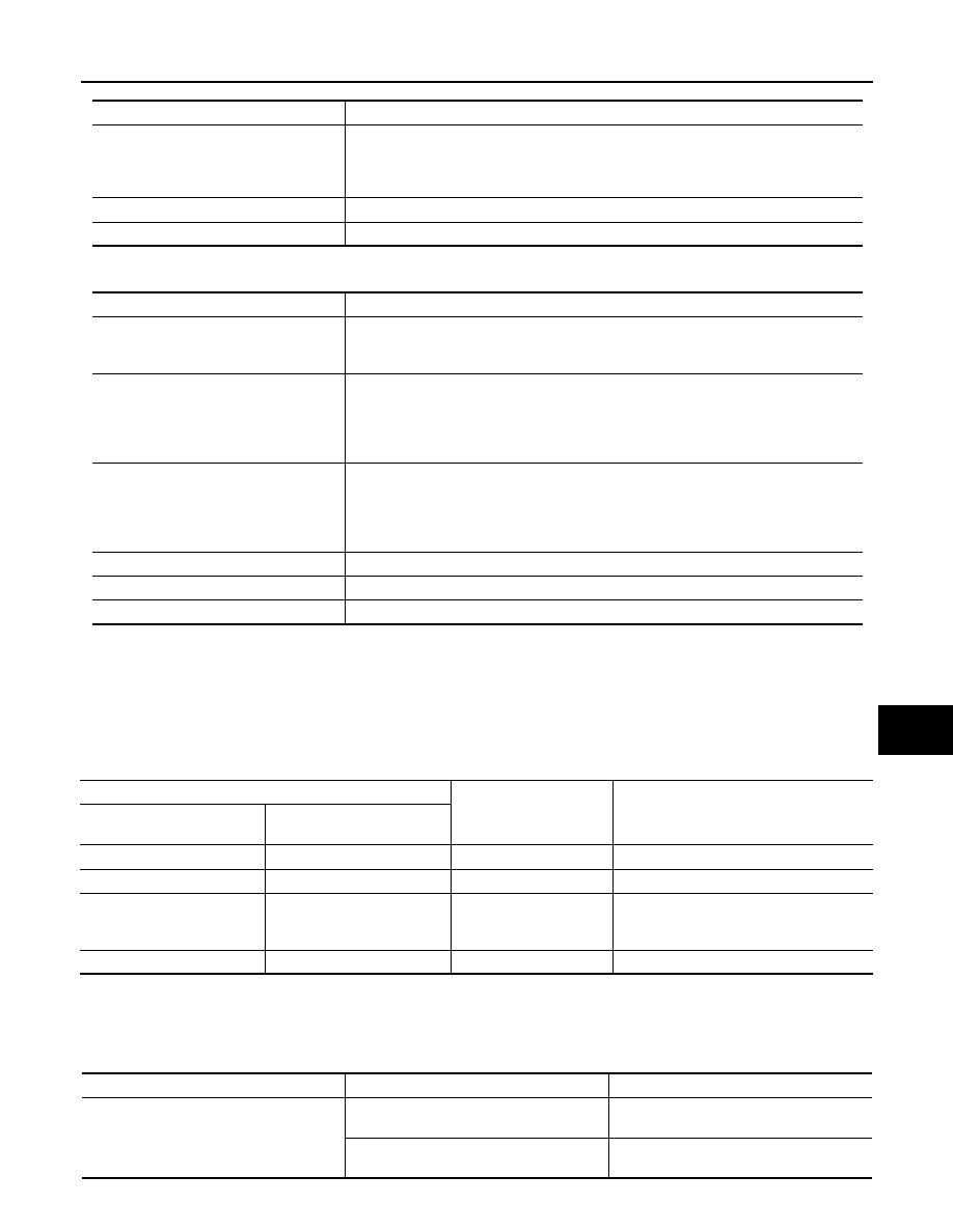
Voltage judgment
IPDM E/R judgment
Operation
Ignition relay contact side
Ignition switch status from
BCM
ON
ON
Ignition relay ON normal
—
OFF
OFF
Ignition relay OFF normal
—
ON
OFF
Ignition relay ON stuck
• Detects DTC “B2098: IGN RELAY ON”
• Turns ON the tail lamp relay for 10 min-
utes
OFF
ON
Ignition relay OFF stuck
Detects DTC “B2099: IGN RELAY OFF”
Ignition switch
Front wiper switch
Front wiper stop position signal
ON
OFF
The front wiper stop position signal (stop
position) cannot be input for 10 seconds.
ON
The front wiper stop position signal does
not change for 10 seconds.