Nissan Cube. Manual - part 817


  Index      Nissan     Nissan Cube (2014 year) - Service and Repair Manual


Search            


Content   ..  815  816  817  818   ..


Nissan Cube. Manual - part 817


B210E STARTER RELAY

SEC-79

< DTC/CIRCUIT DIAGNOSIS >

[WITH INTELLIGENT KEY SYSTEM]

C

D

E

F

G

H

I

J

L

M

A

B

SEC

N

O

P

B210E STARTER RELAY

Description

INFOID:0000000009950187

Located in IPDM E/R, the starter relay runs the starter motor. The starter relay is turned ON by the BCM when
the ignition switch is in the START position. IPDM E/R transmits the starter relay ON signal to BCM via CAN
communication.

DTC Logic

INFOID:0000000009950188

DTC DETECTION LOGIC

NOTE:
• If DTC B210E is displayed with DTC U1000, first perform the trouble diagnosis for DTC U1000. Refer to

BCS-40, "DTC Logic"

.

• If DTC B210E is displayed with DTC B2605, first perform the trouble diagnosis for DTC B2605. Refer to

SEC-65, "DTC Logic"

.

• When IPDM E/R power supply voltage is low (Approx. 7 - 8 V for about 1 second), the DTC B210F may be

detected.

DTC CONFIRMATION PROCEDURE

1.

PERFORM DTC CONFIRMATION PROCEDURE

1.

Turn ignition switch ON under the following conditions and wait 1 second or more.

-

Selector lever is in the P or N position

-

Do not depress brake pedal

2.

Check “Self-diagnosis result” using CONSULT.

Is DTC detected?

YES

>> Go to 

SEC-79, "Diagnosis Procedure"

.

NO

>> INSPECTION END

Diagnosis Procedure

INFOID:0000000009950189

1.

CHECK STARTER RELAY OUTPUT SIGNAL

1.

Check voltage between BCM harness connector and ground.

Is the inspection result normal?

YES

>> GO TO 3.

NO

>> GO TO 2.

2.

CHECK STARTER RELAY OUTPUT SIGNAL CIRCUIT

1.

Turn ignition switch OFF.

2.

Disconnect BCM connector M71.

3.

Disconnect IPDM E/R connector E13.

4.

Check continuity between BCM harness connector and IPDM E/R harness connector.
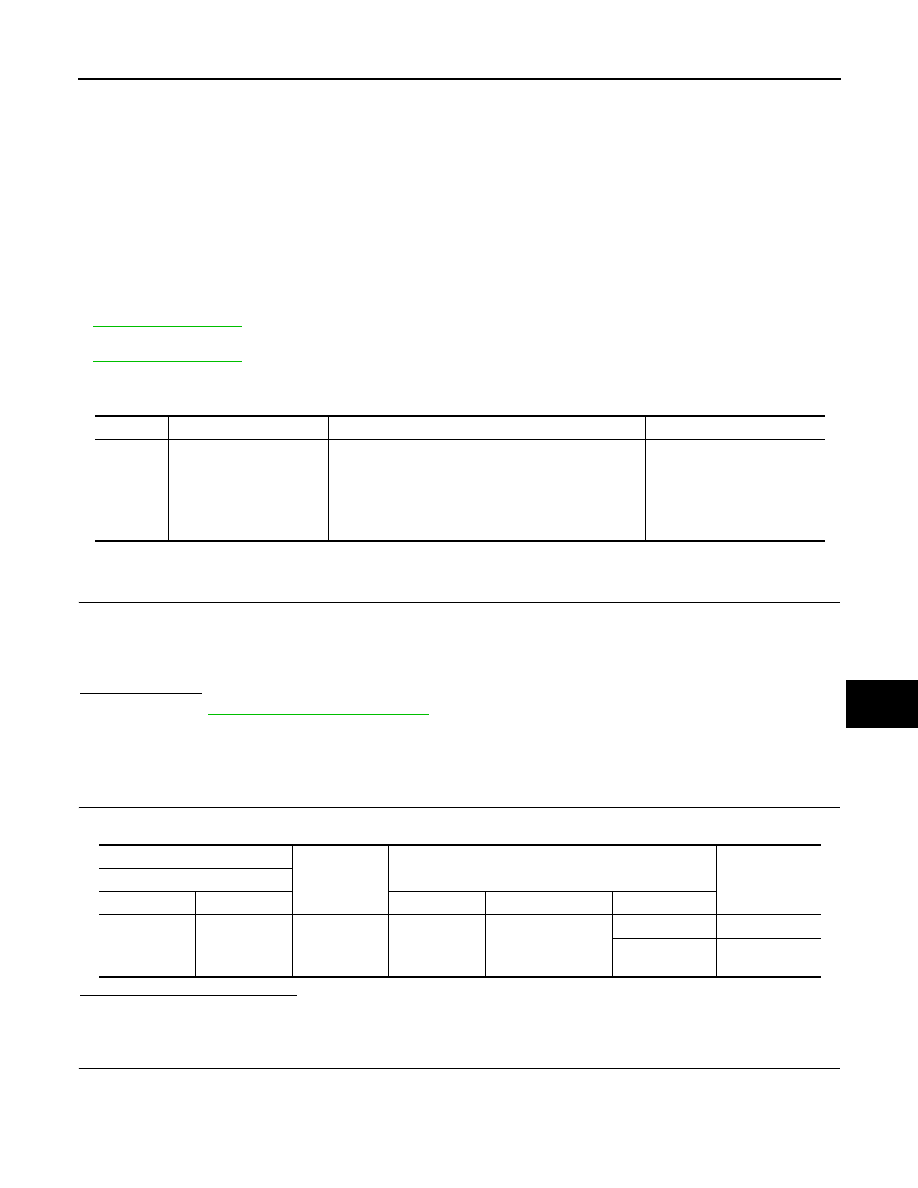
DTC No.

Trouble diagnosis name

DTC detecting condition

Possible cause

B210E

STARTER RELAY OFF

When comparing the following items, a malfunction is 
detected for 1 second or more.
• Starter relay ON signal (CAN) from BCM
• Starter control relay conditions of contact side and 

coil side

• Transmission range switch input

• Harness or connector 

(Starter relay circuit is open 
or short)

• IPDM E/R
• Battery
• BCM

(+)

(–)

Condition

Voltage (V)

(Approx.)

BCM connector

Connector

Terminal

Ignition switch

Brake pedal

Selector lever

M71

97

Ground

ON

Depressed

P or N

Battery voltage

Other than 

above

0

SEC-80

< DTC/CIRCUIT DIAGNOSIS >

[WITH INTELLIGENT KEY SYSTEM]

B210E STARTER RELAY

5.

Check continuity between BCM harness connector and ground.

Is the inspection result normal?

YES

>> Replace IPDM E/R. Refer to 

PCS-34, "Removal and Installation"

.

NO

>> Repair or replace harness.

3.

CHECK STARTER RELAY CIRCUIT

1.

Turn ignition switch OFF.

2.

Disconnect IPDM E/R connector E10.

3.

Check voltage between IPDM E/R harness connector and ground.

Is the inspection result normal?

YES

>> GO TO 4.

NO

>> Check harness for open or short between IPDM E/R and battery. Refer to 

PCS-27, "Wiring Dia-

gram — IPDM E/R —"

.

4.

REPLACE BCM

1.

Replace BCM. Refer to 

SEC-9, "BCM : Work Procedure"

.

2.

Perform DTC CONFIRMATION PROCEDIURE. Refer to 

SEC-79, "DTC Logic"

.

Is the inspection result normal?

YES

>> INSPECTION END

NO

>> Replace IPDM E/R. Refer to 

PCS-34, "Removal and Installation"

.

BCM

IPDM E/R

Continuity

Connector

Terminal

Connector

Terminal

M71

97

E13

30

Existed

BCM

Ground

Continuity

Connector

Terminal

M71

97

Not existed

(+)

(–)

Voltage (V)

(Approx.)

IPDM E/R

Connector

Terminal

E10

4

Ground

Battery voltage

B210F SHIFT POSITION/CLUTCH INTERLOCK SWITCH

SEC-81

< DTC/CIRCUIT DIAGNOSIS >

[WITH INTELLIGENT KEY SYSTEM]

C

D

E

F

G

H

I

J

L

M

A

B

SEC

N

O

P

B210F SHIFT POSITION/CLUTCH INTERLOCK SWITCH

Description

INFOID:0000000009950190

IPDM E/R confirms the shift position with the following signals.
• Transmission range switch
• Shift position signal from BCM (CAN)

DTC Logic

INFOID:0000000009950191

DTC DETECTION LOGIC

NOTE:
• If DTC B210F is displayed with DTC U1000, first perform the trouble diagnosis for DTC U1000. Refer to

BCS-40, "DTC Logic"

.

• If DTC B210F is displayed with DTC B2603, first perform the trouble diagnosis for DTC B2603. Refer to

SEC-57, "DTC Logic"

.

DTC CONFIRMATION PROCEDURE

1.

PERFORM DTC CONFIRMATION PROCEDURE

1.

Turn ignition switch ON under the following conditions and wait 1 second or more.

-

Selector lever is in the P or N position

-

Do not depress brake pedal

2.

Check “Self-diagnosis result” using CONSULT.

Is DTC detected?

YES

>> Go to 

SEC-81, "Diagnosis Procedure"

.

NO

>> INSPECTION END

Diagnosis Procedure

INFOID:0000000009950192

1.

CHECK IPDM E/R INPUT SIGNAL

1.

Turn ignition switch OFF.

2.

Disconnect IPDM E/R connector.

3.

Turn ignition switch ON.

4.

Check voltage between IPDM E/R harness connector and ground.

Is the inspection result normal?

YES

>> Replace IPDM E/R. Refer to 

PCS-34, "Removal and Installation"

.

NO

>> GO TO 2.

2.

CHECK IPDM E/R SIGNAL CIRCUIT SHORT

1.

Disconnect transmission range switch connector.

2.

Check continuity between IPDM E/R harness connector and ground.

DTC No.

Trouble diagnosis name

DTC detecting condition

Possible cause

B210F

INTRLCK/PNP SW ON

There is a difference between input from transmis-
sion range switch and shift position signal from 
BCM.

• Harness or connectors

(Transmission range switch circuit 
is open or shorted)

• Transmission range switch
• IPDM E/R
• BCM

(+)

(–)

Condition

Voltage (V)

(Approx.)

IPDM E/R

Connector

Terminal

E15

47

Ground

Selector lever

N or P position 

Battery voltage

Other than above

0

SEC-82

< DTC/CIRCUIT DIAGNOSIS >

[WITH INTELLIGENT KEY SYSTEM]

B210F SHIFT POSITION/CLUTCH INTERLOCK SWITCH

Is the inspection result normal?

YES

>> Replace IPDM E/R. Refer to 

PCS-34, "Removal and Installation"

.

NO

>> Repair or replace harness.

(+)

(–)

Voltage (V)

(Approx.)

IPDM E/R

Connector

Terminal

E15

47

Ground

0


Content   ..  815  816  817  818   ..